HOW TO RE-ASSEMBLE YOUR COMPANION.
Your Companion is very easy to re-assemble once you reach
your destination. To re-assemble, follow the preceding
procedure in reverse order, noting the following.
1. When re-assembling the front and rear sections of your
Companion, make certain you are on firm, level ground.
Place the front and rear chassis units close together with the
round tube of the front steering section facing the ‘U’
shaped channel of the rear motive unit (see fig 29, page 19)
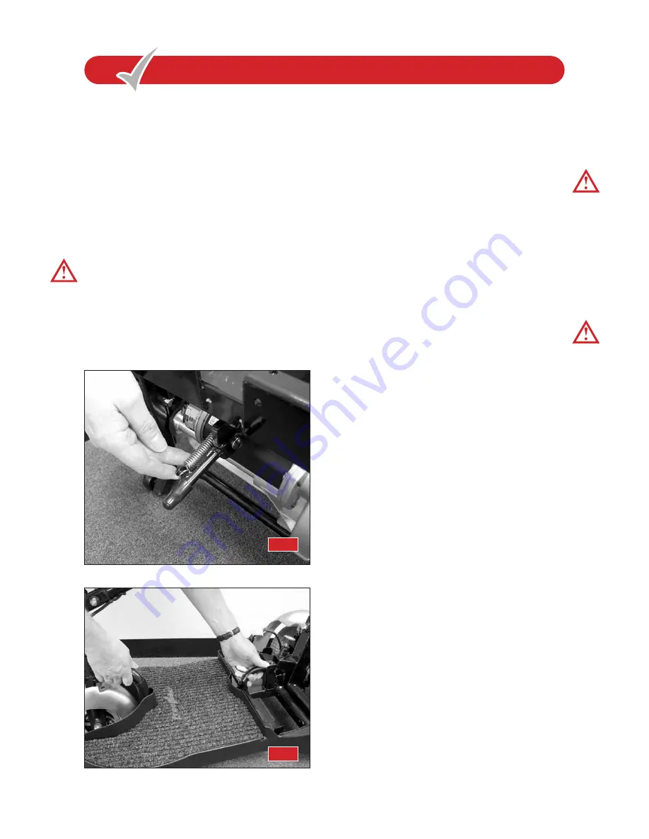
2. Pivot the rear chassis unit backwards onto the anti-tipping
wheels and pull down the central support leg (fig 31),
lower the rear chassis onto the support leg.
Warning:
Do not pivot the rear chassis backwards onto the
plastic body cover, failure to observe this warning will damage
the paint finish.
3. With the aid of the front wheel ‘C’ arch (located behind
the front wheel) and the rear ‘C’ shape handle (located at
the rear of the front steering platform), lift the front
platform and locate it onto the ‘Unshaped channel of the
rear powered unit (fig 32).
4. Lock the two chassis sections together by pushing forward
on the seat mounting post, this allows the rear support leg
to pivot upwards under spring pressure and the two
chassis sections lock together. You will note the locking
mechanism knob moves up and down during this
operation with an audible “click”.
Warning:
Keep hands clear of any ‘pinch’ points during this
operation. Failure to observe this warning could put you into
a dangerous situation.
5. The front and rear chassis parts can now be fully locked
together by rotating the locking mechanism (see fig 27,
page 19) in a clockwise direction indicated by the
“tighten” arrow. Fully tighten the locking mechanism
(approximately four full turns) until the locking pin is fully
located. Pull backwards and forwards on the seat
mounting post to determine that the two chassis parts are
correctly located together, no movement in the two chassis
parts should be found.
Warning:
Failure to fully engage the safety pin mechanism
correctly could result in an accident, please take particular care.
6. Connect the white six pin electrical plug together
(see fig 26, page 19). DO NOT FORCE TOGETHER, you
may have connected it the wrong way round.
7. Replace the two batteries onto the chassis making certain
they are correctly located onto the velcro® fastener.
Replace the two battery plugs into their connectors
(see fig 23 page 18).
8. Replace the black battery cover by locating the four lugs
inside the body covers.
9. Remove the handlebar locking pin (see fig 28 page 19)
and replace it into it’s storage location.
10. Replace your seat by following the instructions on page 6
and 7 of this manual.
When you have re-assembled your Companion, switch the
power key to the ‘on’ position. The battery level gauge will
move and the ‘green’ status light will illuminate. This will
indicate that you have re-connected the battery connectors
correctly. If the battery level indicator and status light do not
illuminate then you have not connected the wiring connectors
correctly (see fig 23 page 18 and fig 26 page 19).
Test the drive function of your machine. Does your
Companion
move forwards and backwards correctly? If
your Scooter does not drive, the freewheel lever may be in
the ‘disengaged’ position, see section ‘Freewheeling your
Companion’ page 9 in this manual.
Important notice:
Your
Freerider
has been designed for
pavement use only,
IT IS NOT A DIRECT REPLACEMENT
FOR A SEAT IN A MOVING VEHICLE
.
Now enjoy your Freerider
20
R E - A S S E M B L I N G Y O U R C O M PA N I O N
R E - A S S E M B L I N G Y O U R C O M PA N I O N
FIG 31
FIG 32


