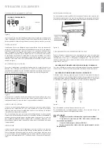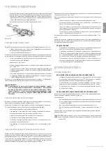
REPLACING THE GRILL INJECTORS (FIG. 14)
•
Remove the injector, by loosening the two screws fastening it in place.
•
Replace the injector, using a 7 mm socket wrench.
A
= ТHЕRМОCOUPLE
B
= SPARK PLUG
Figure 14
• IMPORTANT
RECOMMENDATIONS
•
Under no circumstances should you over-tighten the injectors.
•
After replacing all the injectors check that they are air-tight.
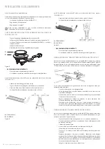
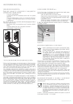
REDUCED FLOW ADJUSTMENT FOR HOB BURNERS (SETTING
HOB BURNER MINIMUM LEVELS)
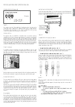
If the cooker is intended to work on bottled gas (butane/propane), the thermostat by-
pass must be screwed right down. A cooker can be equipped with type A taps with a
by-pass inside (accessed by inserting a small screwdriver into the rod) or type B taps,
with a by-pass on the right (accessed directly); see fi gure 15.
Рисунок 15
If the cooker is intended to work on natural gas, proceed as follows, no matter what
type of tap is used:
•
Ignite the burner and turn the knob to the maximum fl ame position.
•
Remove the knob by pulling it towards you, without putting pressure on the
front panel of the cooker to avoid damage.
•
Using a small screwdriver, loosen the regulating screw, turning it by
approximately 3 notches, moving anti-clockwise.
•
Turn the tap rod anti-clockwise again until it stops. In this position the fl ame
will be at its maximum level.
•
Very slowly screw the by-pass back in, without pushing the screwdriver, until
the fl ame reduces to three-quarters of its maximum size. Make sure that the
fl ame is suffi
ciently stable, even with moderate draughts.
REDUCED FLOW ADJUSTMENT FOR OVEN BURNERS (SETTING
OVEN BURNER MINIMUM LEVELS)
If the cooker is intended to run on bottled gas (butane/propane), the thermostat
by-pass must be screwed right down. If the cooker is intended to run on natural gas,
proceed as follows to adjust the minimal fl ame, no matter what type of tap is used:
•
Remove the oven base (by pushing it to the back wall and lifting).
•
Ignite the oven burner, turning the knob pointer to the maximum setting.
•
Close the oven door.
•
Access the thermostat or tap by-pass (see fi g. 16).
•
Loosen the adjustment screw by approximately three notches.
•
In 5–6 minutes, turn the knob pointer to the maximum setting.
ADJUSTING FOR DIFFERENT TYPES OF GAS
If the cooker is not already pre-set to operate with the type of gas available, it must be
converted by following these steps:
•
Replace the injectors (see APPENDIX 1);
•
Regulate the primary air fl ow;
•
Regulate the minimum fl ow settings for all burners.
Note: after every such adaptation, you must stick to the nameplate the name
of the new gas type to which the cooker has been set.
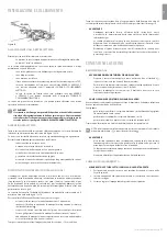
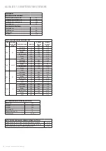
REPLACING THE HOB BURNER INJECTORS (FIG 12)
•
Remove, the shelf, the burner caps (A) and the burners (B).
•
Unscrew and remove the injector, which is found at the bottom of every
injector holder (C).
•
Replace injectors as shown in the table in Attachment 1, and screw and
tighten them all the way.
•
Check that injectors are air-tight.
•
Put the burners, the burner caps and the shelf back into place.
22
INSTALLATION AND SWITCHING ON
A
C
B
INSTALLATION AND SWITCHING ON
Figure 12
• IMPOTRTANT
RECOMMENDATIONS
•
Under no circumstances should you over-tighten the injectors.
•
After replacing all the injectors, check that they are air-tight.
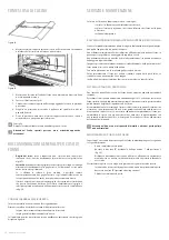
REPLACING AN OVEN INJECTOR (FIG. 13)
•
Loosen the screw securing the cooker base.
•
Remove the cooker base (by pushing it back and lifting).
•
Remove the oven injector, after fi rst loosening the screw fastening it in place.
•
Replace the injector, using a 7 mm socket wrench.
A
= ТHЕRМОCOUPLE
B
= SPARK PLUG
Figure 13
Summary of Contents for PP96GEE50
Page 63: ......


