Descriptions of LEFT and RIGHT are from the point of view of standing
behind the equipment facing the front
11
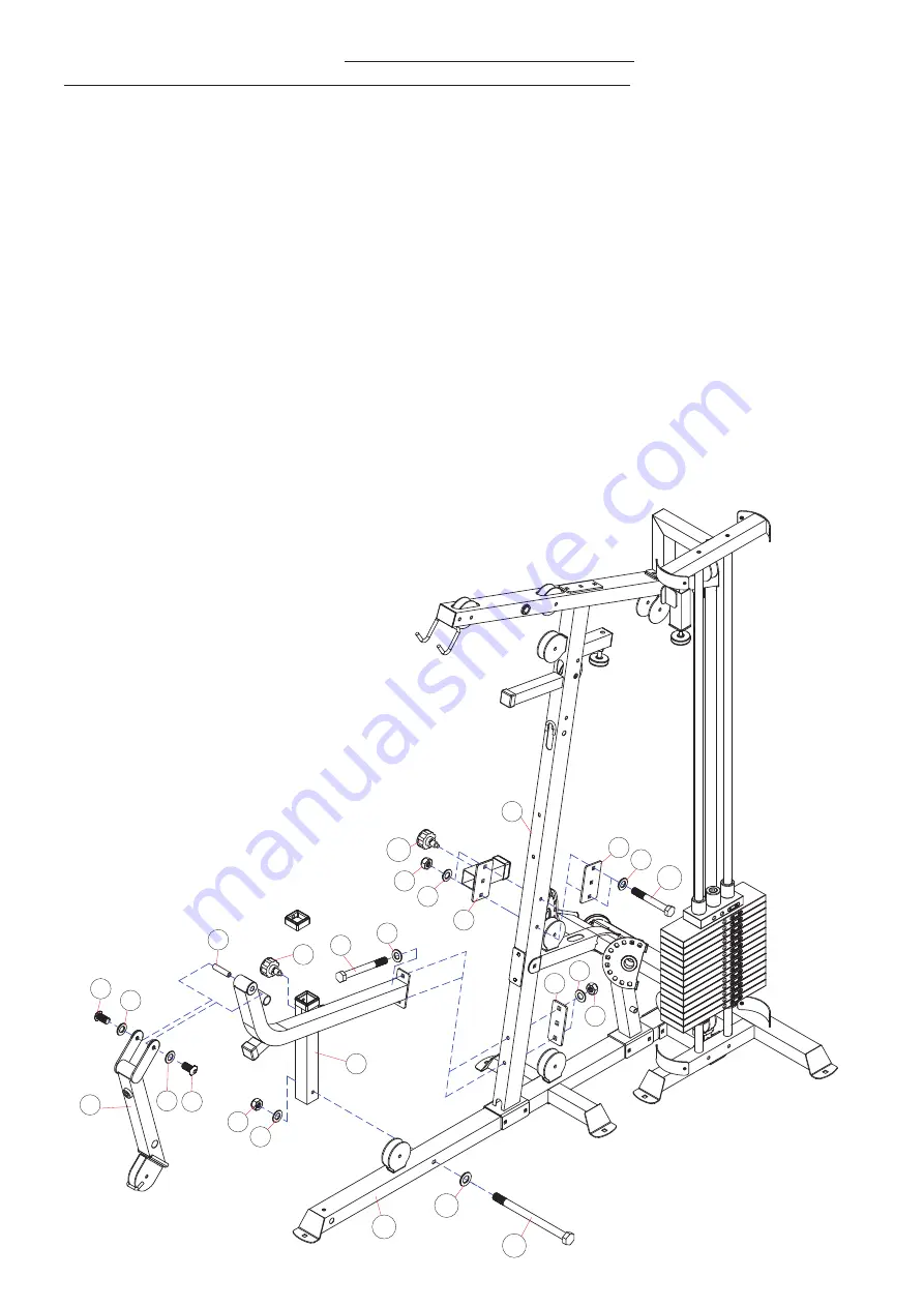
ASSEMBLY DIAGRAM 6
USE A PARTNER TO HELP WITH THIS STEP
REMEMBER: Only hand tighten all nuts and bolts until whole
&&Ͳ
X
ϰ
is assembled
1.
Ensuring correct orientation, position the ADJUSTABLE BACKREST SUPPORT (19) over the mid-point bolt holes on the
right side of the FRONT VERTICAL FRAME (3) and a BRACKET (52) at the same point on the left.
2.
Connect all parts using two HEX BOLT M10X75 (106), four WASHER10 (92) and two AIRCRAFT NUT M10 (97)
3.
Attach a SLEEVE (84) to the rear of the ADJUSTABLE BACKREST SUPPORT (19) (
Skip this step if pre-assembled)
4.
Position the FRONT SUPPORT FRAME (6) so the vertical post sits to the right of the BASE FRAME (13) and the rear
bracket lines up with the lowest bolt holes on the FRONT VERTICAL FRAME (3)
5.
Connect the FRONT SUPPORT FRAME (6) to the BASE FRAME (13) using a HEX BOLT M10X135 (110), two WASHER10
(92) and an AIRCRAFT NUT M10 (97)
6.
Connect the FRONT SUPPORT FRAME (6) to the FRONT VERTICAL FRAME (3) and through a BRACKET (124) positioned
at the rear, using two HEX BOLT M10X95 (109), four WASHER10 (92) and two AIRCRAFT NUT M10 (97)
7.
Assemble the AXEL (74) using two GROOVE BALL BEARING (76) and two SHELL BEARING (29). Insert a RUBBER
BUMPER (59) into the front of the LEG DEVELOPER (26) using a PHILIPS SCREW (122)
(See the exploded diagram for
more detail, skip this step if pre-assembled)
8.
Slot the AXEL (74) through the front of the FRONT SUPPORT FRAME (6). Position the LEG DEVELOPER (26) over the
ends of the AXEL (74), connecting with two ALLEN BOLT M10X16 (119) and two WASHER10 (92)
9.
Clip a LOCK KNOB (68) to the right side of the ADJUSTABLE BACKREST SUPPORT (19) and also to the top right of the
vertical post on the FRONT SUPPORT FRAME (6)


