Descriptions of LEFT and RIGHT are from the point of view of standing
behind the equipment facing the front
9
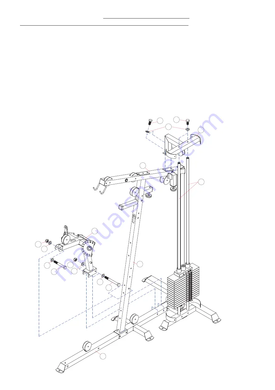
ASSEMBLY DIAGRAM 4
USE A PARTNER TO HELP WITH THIS STEP
REMEMBER: Only hand tighten all nuts and bolts until whole
&&Ͳ
X
ϰ
is assembled
1.
Ensuring correct orientation, position the BUTTERFLY SUPPORT (21) between the BASE FRAME (13) and the rear of
the FRONT VERTICAL FRAME (3)
2.
Connect the BUTTERFLY SUPPORT (21) to the BASE FRAME (13) using two HEX BOLT M10X95 (109), four WASHER10
(92) and two AIRCRAFT NUT M10 (97)
3.
Connect the BUTTERFLY SUPPORT (21) to the FRONT VERTICAL FRAME (3) using HEX BOLT M10X75 (106), two
WASHER10 (92) and an AIRCRAFT NUT M10 (97)
4.
Ensuring correct orientation, position the UPPER GUIDE ROD FRAME (8) over the top of the GUIDE RODS (5) and the
UPPER FRAME (4)
5.
Connect the UPPER GUIDE ROD FRAME (8) to the GUIDE RODS (5) using two HEX BOLT M10X20 (99) and two
WASHER10 (92)
.
Connect the UPPER GUIDE ROD FRAME (8) to the UPPER FRAME (4) using two HEX BOLT M10X16
(98) and two WASHER10 (92)


