background image

11

Hinweis: 


Die Folie ist elektrisch nur an den vormontierten Kontakten zu  
kontaktieren.

Der Trafo kann Auf- oder Unterputz (in UP-Dose mind. IPX4) verbaut  
werden.  Dazu ist ein Mindestabstand von 50 mm zur Folie einzuhalten.
Die maximale Leitungslänge auf der Sekundärseite des Trafos darf maximal 
2000 mm betragen.
 
Die Leitungslänge auf der Netzspannungsseite darf inklusive aller mög-
lichen Verzweigungen maximal 10 m betragen.
Die Verlegung der elektrischen Leitungen hat nach der aktuell gültigen 
DIN VDE 0100 zu erfolgen (Netzleitungen doppelt isoliert, mind. 2,5 mm

2


Leitungsquerschnitt, Verwendung der beigestellten Anschlussklemmen).
Nun den Trafo an das optional mitgelieferte Regelgerät anschließen (siehe 
Installationanweisung Regelgerät).


3.4   Inbetriebnahme

Nach einer Trockenzeit von mind. 24 Stunden das hicoTHERM®-Heizungsset 
erstmals für 15 Minuten aufheizen. Das Heizsystem ist nun betriebsbereit. 
Bringen Sie nun das mitgelieferte Warnschild in unmittelbarer Nähe der 
Heizfolie gut sichtbar an und hinterlegen Sie die Bedienungsanleitung im 
Verteilerkasten.

Note: 


The electrical contact for the film must be established via the pre- 
assembled contacts

The transformer can be surface-mounted or flush-mounted (in a 


flush-mounted box, at least IPX4). It must be at least 50 mm away from 
the film. The maximum conductor length on the secondary side of the  
transformer is 2 000 mm.

The maximum conductor length on the mains voltage side, including all 
possible junctions, is 10 m.
The electrical conductors must be installed in accordance with the latest ver-
sion of DIN VDE 0100 (mains conductors with double insulation, conductor 
cross-section at least 2.5 mm², use of the connection terminals supplied). 
Now connect the transformer to the control unit that is provided as an opti-
onal extra (see the installation instructions about the control unit).


3.4   Start-up

Heat the hicoTHERM® heating kit up for the first time for 15 minutes after 
a drying period of at least 24 hours. The heating system is now ready for 
operation. Attach the warning sign supplied with the kit now in a high-
ly visible place in the immediate vicinity of the heating film and put the  
instructions in the circuit breaker panel box.

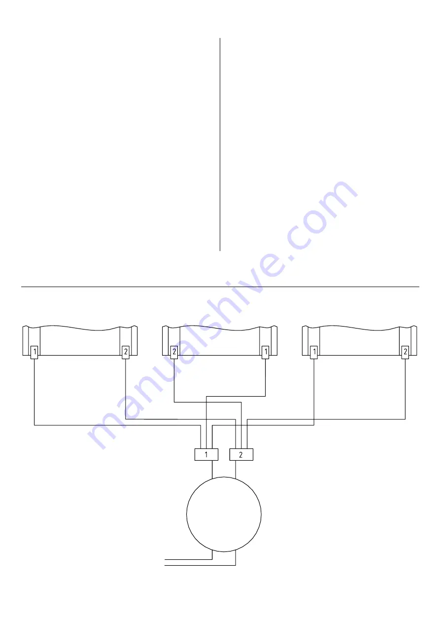
Einbausituation mit bis zu 3 Bahnen

Installation configuration with up to 3 sections of heating film.

Heating film

Heating film

Heating film

Heizfolie

Heizfolie

Heizfolie

SEC

24 V

PRI

230 V

Trafo

300 W

Summary of Contents for hicoTHERM 110

Page 1: ...d Montageanweisung Installation and operating instructions hicoTHERM 110 Heizungsset Heating kit hicoTHERM 60 Temperierungs und Sanierungsset Temperature regulation and renovation kit hicoTHERM 220 He...

Page 2: ...2 MONTAGE SKIZZE INSTALLATION DRAWING Heizfolie Regelger t Thermof hler Trafo Bitte unbedingt aufbewahren Please make sure you keep this Heating film Control unit Temperature sensor Transformer...

Page 3: ...4 Inbetriebnahme 4 TECHNISCHE DATEN 5 GEW HRLEISTUNG UND GARANTIE 6 GARANTIE KARTE Installation and operating instructions hicoTHERM 60 Temperatureregulationandrenovationkit hicoTHERM 110 Heating kit...

Page 4: ...in Hier ist eine 1 CONFIGURATIONS AVAILABLE The hicoTHERM 60 temperature regulation and renovation kit and the hi coTHERM 110 220 heating kit are supplied in two different configurations 1 1 Kit conte...

Page 5: ...ler heating and or floor temperature regulation systems The products need to be checked to make sure they are designed for such systems with particular attention being paid to the information provided...

Page 6: ...ystem nach f nf Jahren von einem zugelassenen Elektrofachmann berpr fen zu lassen It is generally possible for holes to be made in the heating film subsequently Care needs to be taken in this context...

Page 7: ...and floors Special instructions for hicoTHERM 110 220 Attention needs to be paid to the floor structure too here The felt layer on the heating film acts as minimum insulation and improves heat radiati...

Page 8: ...edurchgangskoeffizienten sind einzu halten Es d rfen nur genormte f r Fu bodenheizung geeignete D mm area If necessary the heating film can be divided once at right angles to the copper conductors A m...

Page 9: ...st not be com pressible by more than 5 mm If there are several layers the compressibility of the individual layers is added together Umax W m2 L Rmin m2 K W Intermediate ceilings above heated rooms 1...

Page 10: ...Betrieb nehmen other the individual sections and the copper contact strips must not touch or cross each other See Section 3 3 Electrical connection for information about installation of the controlle...

Page 11: ...m must be established via the pre assembled contacts The transformer can be surface mounted or flush mounted in a flush mounted box at least IPX4 It must be at least 50 mm away from the film The maxim...

Page 12: ...itungen befolgen e Schutzklasse II 4 TECHNICAL DATA Mains voltage 230 V AC Power input 1 3 A per toroidal transformer Output hicoTHERM heating film 60 W m2 hicoTHERM 60 110 W m2 hicoTHERM 110 220 W m2...

Page 13: ...aus der Garantie ausgeschlossen Ausgeschlossen sind auch Anspr che auf Garantieleistungen solange und soweit diese au erhalb der europ ischen Union zu erbringen w ren 5 WARRANTY AND GARANTEE 1 We pro...

Page 14: ...r merken Einbauort Raum Fitting Room ________________________________________ Decke Ceiling Wand Wall Boden Floor Test report The warranty only applies if the warranty card has been filled in complete...

Page 15: ...00 W alternativ 700 1000 und 2000 W toroidal transformator 300 W alternative 700 1000 and 2000 W W rmepaket Folie Heating package film Temperaturf hler temperature sensor und Temperaturregler and temp...

Page 16: ...vorbehalten Subject to technical amendment HS 3 09 14 005 WY Artikel Nummer Article number 0793999901 Frenzelit Werke GmbH P O Box 11 40 95456 Bad Berneck Germany Phone 49 9273 72 111 Fax 49 9273 72...

Reviews: