7
3 MONTAGE
3.1 Vorbereitung
Die hicoTHERM®-Sets sind im Innenraumbereich geeignet für Außen-,
Innenwände, Böden und Decken.
Die Auswahl der zu verwendeten Heizfläche richtet sich nach den später
beabsichtigten Stellflächen für Möbel und Beläge sowie einer optimalen
Wärmeeinbringung. Dazu sei noch einmal auf den Punkt 2.1 der Bedie-
nungsanleitung verwiesen.
Bei Außenwänden und Böden ist auf eine gute Wärmedämmung der
Mauerkonstruktion zu achten.
Speziell für hicoTHERM® 110/220:
Ist auch auf die Bodenkonstruktion zu achten. Die Filzschicht auf der
Heizfolie dient als Mindestdämmung und verbessert die Wärmeab-
strahlung zum Raum. Dabei ist immer die Filzseite zur dämmenden
Fläche zu richten.
Die hicoTHERM®-Heizfolie ist nicht für den Verbau als Speicherheizung
konzipiert und damit nicht für den Verbau in Estrich zu verwenden. Je nä-
her die Heizfolie zur Raumoberfläche verbaut wird, desto schneller reagiert
das Heizsystem und gibt die wohltuende Wärmestrahlung in den Raum ab.
Zur Erleichterung ihrer persönlichen Planung und Dokumentation der
Verlegearbeiten sollten Sie die Montage-Skizze (Seite 8) benutzen.
Es wird empfohlen, vor Verlegung die Folien entsprechend der Montage-
Skizze zuzuschneiden. Die Folie ist elektrisch stets an den vormontierten
Kontakten zu kontaktieren.
3 INSTALLATION
3.1 General preparation
The hicoTHERM® kits are suitable for outside / inside walls, floors and
ceilings in building interiors.
The heating area chosen is determined on the basis, firstly, of where
furniture and coverings are planned subsequently and, secondly, of
optimum heat distribution. Attention is again drawn to point 2.1 of these
instructions in this context.
Care must be taken to make sure that the wall structure has good heat
insulation in the case of outside walls and floors.
Special instructions for hicoTHERM® 110/220:
Attention needs to be paid to the floor structure too here. The felt layer
on the heating film acts as minimum insulation and improves heat
radiation into the room. The felt side must always face the surface that
requires insulation.
The hicoTHERM® heating film is not designed for installation as a storage
heating system and should not therefore be incorporated in screed. The
closer the heating film is to the room surface, the faster the heating system
responds and the faster the pleasant radiant heat reaches the room.
You should use the installation drawing (page 8) to facilitate your personal
planning and to document the installation work.
It is recommended that the film is cut to size in accordance with the
installation drawing before the film is installed. The pre-assembled
contacts must always be used to establish the necessary electrical contacts.
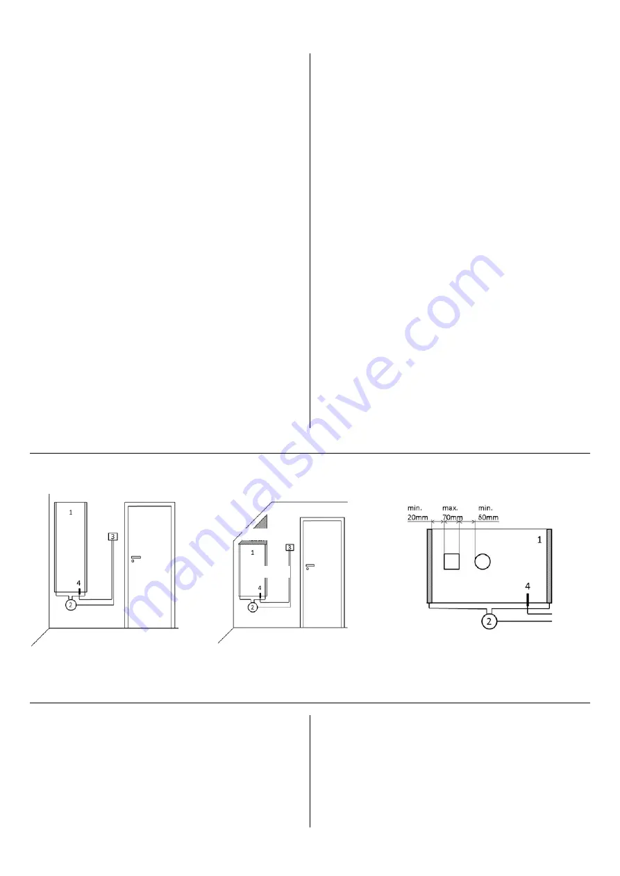
Allgemeiner Wandaufbau
General wall structure
Folienbeschnitt
Film cutting
Folienaussparungen
Film cutout
(1) Heizungsfolie
(2) Trafo
(3) Regler
(4) Fühler
(1) Heating film
(2) Transformer
(3) Controller
(4) Sensor
3.2 Verlegung
Dieser Abschnitt bezieht sich auf die Verlegung der Folie und des Trafos.
Die Verlegung der Leitungen und der elektrischen Anschlüsse ist im
Abschnitt 3.3 Elektrischer Anschluss erklärt. Berücksichtigen Sie die Min-
destverarbeitungstemperatur von +5°C.
Bei Wänden unterhalb von 2,3 m Höhe und in Decken, die weniger als 45°
zur Senkrechten geneigt sind, sollte die Heizfolie ca. 15 cm kürzer als die
3.2 Installation
This section relates to installation of the film and the transformer.
Installation of the supply lines and the electrical connections is explained
in Section 3.3 Electrical connection. Please note that the minimum
processing temperature is +5°C.
When walls are less than 2.3 m high and ceilings slope less than 45°, the
heating film should be about 15 cm shorter than the length of the installation
falsch / wrong
richtig / right


