Page 103
Trouble Shooting
Service Manual Deli Multisserie form 9123560 rev. 02/2017
GND
UI
N
TXB
1
2
3
4
5
6
7
8
9
10
11
12
13
14
J3
FC14HF
RXA
RXB
TXA
12
V
24V
12V
24V
12V
1
2
13
14
RXD / TXD
RXD / TXD
Ribbon
cable
POWER SUPPLY
CPU board
Power&I/O board
Slave board
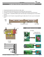
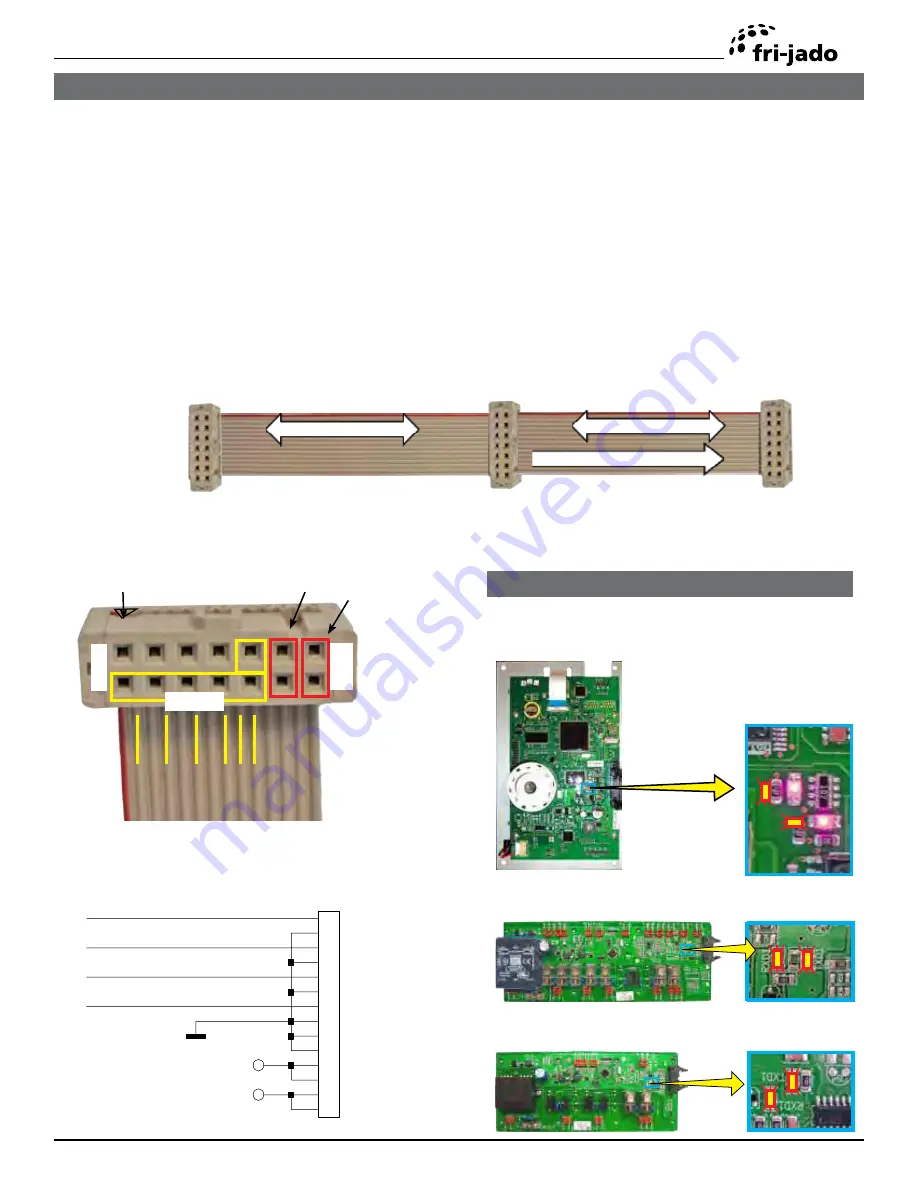
COMMUNICATION BETWEEN THE ELECTRONIC BOARDS
Mark
GND
CPU board
Transmit (TXD) and
Receive (RXD) signals
LED Positions on the boards
Schematic
overview
Power & I/O board
Extension board
1. All boards are connected to each other with a ribbon cable.
2. The CPU board communicates by means of a serial protocol with the other boards.
3. Therefore you wil see 2 LEDs, named RXD and TXD, flashing (in high frequency) close to the sockets.
4. In case the LED’s on a board flash differently from the other boards, this board might have a communication
problem.
5. The power for the CPU board is also provided through the ribbon cable. The initial source is the Power&I/O
board.


