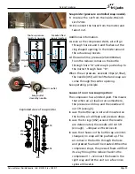
Page 41
Service Procedures
Service Manual Deli Multisserie form 9123560 rev. 02/2017
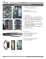
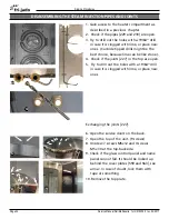
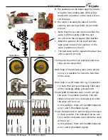
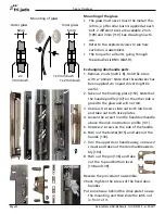
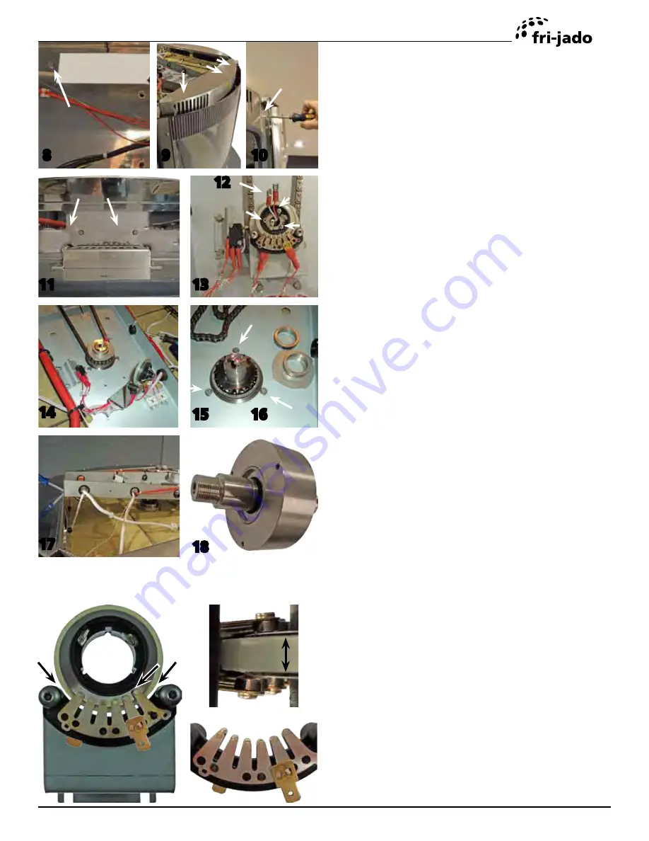
6. Unscrew 7 screws M5x12 and 4 screws
M5x 30 at the top-backside.
7. Unscrew 2 bolts M5x10 at the backside and
take out the top plate.
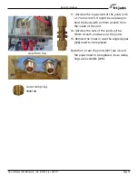
8. Loosen the screw on the back from the
chain box [557] 4 turns.
9. Unscrew 3 screws at the front top.
10. Pull a screwdriver in the seam of the curved
frontpanel [567] and push it out.
11. Unscrew 2 bolts from the chain box at the
front side. Metric 8.
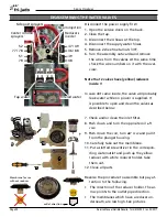
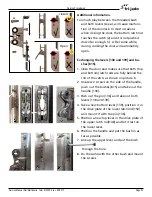
12. Disconnect the core probe wires.
13. Put some cleaning tissue in the hole of the
rotor shaft and unscrew the 3 screws from
the sliding ring. (M3x10).
14.Unscrew the brackets of the sliding contacts
[324] and rotor position switch [323]. The
sliding ring can stay in the sliding contact.
15. Remove the core sensor (from the inside),
the position cam disc [301] with the several
spacers and the chain from the shaft.
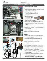
16. Unscrew 3 bolts. (Metric 8)
17. Lift up the chain box and lock it. Be carefull
with the wiring. It might be necessary to
disconnect some.
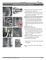
18. Lift and take out the shaft and bearing as-
sembly [310].
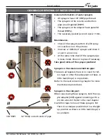
Reverse the procedure to assemble but take
care of a proper adjustment of the sliding
ring and contacts.
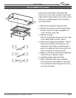
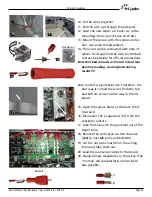
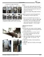
The 3 arrows point at places where 1-2 mm
clearance should be observed. It is also very
important that the sliding ring is moun-
ted in the middle of the contacts. See side
view detail. Note that the contacts differ in
lenght. On the left side, the bottom contact
is longer than the top one! On the right
side it is shorter!
8
side view detail
Take care of clearences!!
9
10
11
13
14
15
17
18
12
16

