Page 57
Electrical tests
Service Manual Deli Multisserie form 9123560 rev. 02/2017
0,15
Ω
500V
!
Insulation test
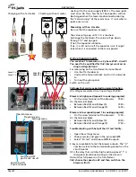
The speed transformer.
General.
This transformer has big copper wires and therefore the
resistance is very low.
For this reason it is difficult to measure the right value
because of deviations in the multimeter and contact
resistances of the test probes.
Therefore it is recommended to define this measu-
rement error as good as possible with the following
instruction.
Prevention of measurement errors!
• Put both test probes on the same terminal or in this
case the same wire.
• Write down the reading. For example 0,22 Ω.
• Subtract this value from the next measurements.
For example, the reading of the primary coil is 0,64 Ω.
The real value is 0,64 - 0,22 = 0,42 Ω.
Tip: Insulation testers (Megger) often have a very good
resistance meter.
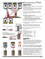
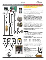
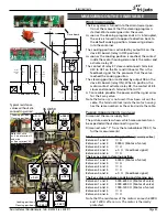
Measuring the transformer coils. (see overview)
Disconnect the wires from the terminal block first.
The transformer has 3 separated coils. 1 Primary coil
and 2 secundary coils.
Resistance:
Primary coil (black - white): 0,42 Ω
Secundary coil (Yellow-Or):
0,15 Ω
Secundary coil (Or - Red):
0,49 Ω
Insulation:
Prim.-sec.1 (Black-Red):
∞
Ω
Prim.-sec.2 (White- Yellow)
∞
Ω
Sec.1-sec.2 (Orange-Orange)
∞
Ω
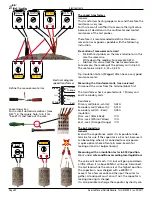
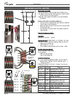
The 6µF capacitors
General
Even with a capacitance meter it is impossible to de-
termine for sure if the capacitor is ok or not, because it
can be leaking when it is connected to mains power.
A quick optical check often tells more. Search for
leaking oil and / or bulges (lumps).
Measuring with an insulation tester in 500V position.
Work under
safe conditions according local legislation!
The value will not reach
∞
Ω, but will go up and down
a little. When it is above 50MΩ it wil be ok. Disconnect
the test leads while the value is at the highest position.
The capacitor is now charged with ± 500VDC!!
Leave it for a few seconds and then put the wires to-
gether. A loud spark must arise. If not, the capacitor is
leaking (loosing its charge).
It is also possible to charge the capacitor by shortly con-
0,42
Ω
0,49
Ω
500V
!
Insulation test
∞
MΩ
500V
!
Insulation test
∞
MΩ
∞
MΩ
black-white red-or-or-yellow
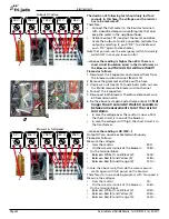
Define the measurement error.
Electrical diagram
speed transformer
Loosening wires:
Push a small slotted screwdriver (max
5/32”) in the square hole, turn it (or
“bend” it) and take out the wire.
!
Insulation test
>50 MΩ
*
!
6 µF
500V
500V
208V
175V
Black
Yellow
Orange
Orange
43V
White
Red

