Page 64
Electrical tests
Service Manual Deli Multisserie form 9123560 rev. 02/2017
V~
V~
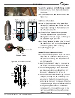
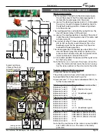
Relay K7 and K8
Between A1 and A2 ± 36 kΩ
Power and I/O board inputs
Between X16 and X17
±5 kΩ
Between X30 and X31
±5 kΩ
Active measurements
(Voltages, ~ and =)
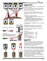
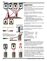
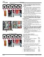
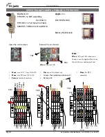
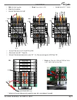
When the unit is switched on, the valve will turn into
cooking position or is already there. Check the vol-
tages with the values as shown on the picture.
Put the valve in cleaning position with help of the I/O
testfacility -->Activate X3 X4 on the MFMB board.
Check the voltages with the values as shown on the
picture.
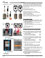
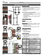
Trouble shooting.
Proceed as follows:
(X3-N means “between terminal X3 and
terminal X11 (marked “N”) on the slave board)
1 3 4 5 6
1 3 4
5
6
PE
101
107
54
53
95
98
101
36 48 50
Note that wire
nr. 3 is on terminal 2
and wire
nr 4 on terminal 3!!!
K7 K8
TB2
Cooking position->
Cleaning position->
Cooking pos->
Cleaning pos->
Typical voltages
V~
V~
208V~
0V~
0V~
208V~
208V~
0V~
0V~
208V~
V=
V=
0V=
3,7V=
3,7V=
0V=
X16
X17
X30
X31
54
53
98
95
K7 & K8
Power & I/O board inputs
Cooking pos->
Cleaning pos->
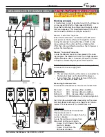
Measure
Value
If Not ok
Valve in cooking position
X3 - N
(X11)
208V~ Board failure or N & L (X10)
exchanged on mains terminals
of board.
Wire 3 - N
208V~ Wire 48 or 3 disconnected
Wire 3 - 1
208V~ Wire 1 disconnected from Neu-
tral.
Coil K7
208V~ Valve problem
Contact K7 0V=
Relay problem
X30 – x31
0V=
Wiring problem
If all ok
Board problem (input side)
Valve in cleaning position
X4 to N
208V~ Board failure or N & L ex-
changed on mains terminals of
board.
Wire 4 - N
208V~ Wire 50 or 4 disconnected
Wire 4 - 1
208V~ Wire 1 disconnected from Neu-
tral.
Coil K8
208V~ Valve problem
Contact K8 0V=
Relay problem
X16 – X17
0V=
Wiring problem
If all ok
Board problem (input side)
Fuse 0,5A 5x20mm


