Page 66
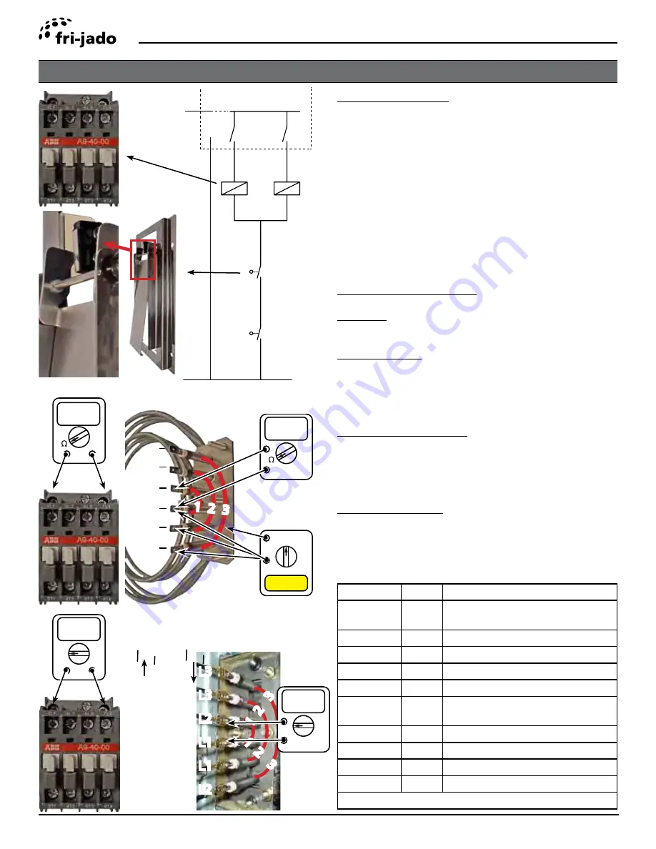
Electrical tests
Service Manual Deli Multisserie form 9123560 rev. 02/2017
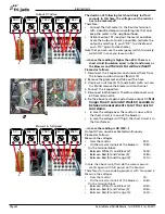
X10
X9
A1
A1
A2
A2
3
3
1
1
K6
K3
41
42
58
44
56
X14
37
40
X15
N
L
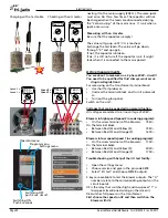
Power and I/O board
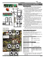
Working principle.
The temperature is measured by two PT1000 sensors.
The upper sensor controls the top heater and the lower
sensor controls the lower heater.
Therefore, two separate contacters are controlled by
the board.
Blower malfunction overheat protection!
• A vane switch is mounted on each blower to detect
the minimum rotationspeed.
• Both switches are put in series with the neutral side
of the contactors.
• The contacts only close when the blowers speed is
high enough.
Passive measurements.
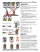
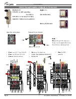
Contactor
Between A1 and A2
±600Ω
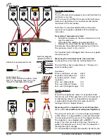
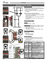
Heating element
(208V, 10kW -> 3x 3,33kW -> 3x 16A)
The picture shows how the heating elements are con-
nected on the terminals.
• Each element is ± 13Ω
• The insulation of each element has to be >1MΩ.
Active measurements
On the contactor coils 208V
On the heater:
208V on each element.
16A on each element.
Trouble shooting.
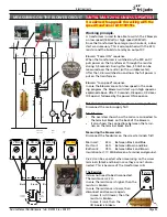
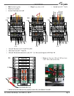
Start up a cooking program and be sure that the set
temperature is higher than the cooking cavity -->
“asking for heat”.
Proceed as follows:
(X9-N means “between X9 and terminal
X15 (marked “N”)
MEASURING ON THE HEATERS
500V
!
Insulation test
>1MΩ
±600Ω
1 2 3
1 2 3
V~
3x
208V~
1 2 3
3x
± 13Ω
3 separate
heaters
L3
L3
L2
L1
L1
L2
V~
208V~
Measure
Value
If Not ok
X9 - N
208V~ Board failure or N & L ex-
changed on X14 and X15.
K3(A1) - N 208V~ Wire 42 disconnected
K3(A2) - N 0V~
Open vane switch or loose wire.
K3 = On?
Broken contacter
X10 - N
208V~ Board failure or N & L ex-
changed on X14 and X15.
K6(A1) - N 208V~ Wire 41 disconnected
K6(A2) - N 0V~
Open vane switch or loose wire.
K6 = ON?
Broken contacter
Stop the cooking program!
L1-L2-L3
L1
L1
L2
L3
L3
L2
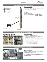
23
22
24
28
29
30
upper
31
32
33
21
20
19
lower heater
Wire nr
.
Phase
Wire nr
.
Phase

