Page 68
Electrical tests
Service Manual Deli Multisserie form 9123560 rev. 02/2017
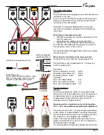
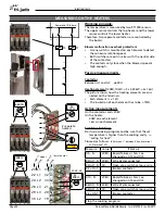
±310k
Ω
±675
Ω
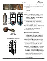
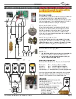
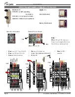
Working principle.
There are 6 watervalves mounted in the unit. A double
inlet valve and a quadruple valve.
Outputs on the Slave I/O board
Relay K5 switches the 2 waterinlet valves and is control-
led by output X8 .
Output X7 controls the valve for the watersprayers in
the center.
Output X6 controls the valve for the watersprayers in
the side post.
Outputs on the Power & I/O board
Output X8 controls the two watervalves for the steam
production.
These two valves are connected parallel and have a
reducer mounted inside.
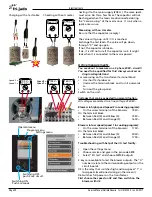
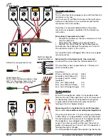
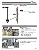
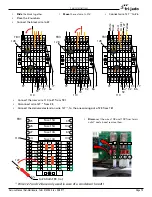
Working principle.
The motor is controlled by output X9 of the Slave I/O
board.
Two cam switches give the feed back signals for the
open or closed position.
The motor resistance is ± 10 kΩ and can also be measu-
red in circuit.
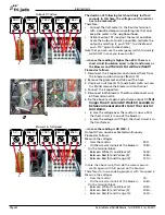
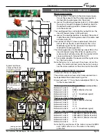
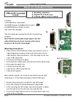
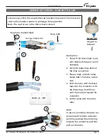
Working principle.
Two independant switches control the safety circuit.
• The emergency switch
• High limit thermostat
Both switches are in series with two contacters.
These contacters switch OFF all phases and Neutral
lines in case the high limit trips or when the emergency
switch is pushed in.
214
Ω
107 Ω
in circuit!
10 k
Ω
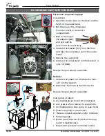
MEASURING ON THE WATERVALVES
K5
MEASURING ON THE AIRVALVE (VENT)
MEASURING ON THE SAFETY CIRCUIT

