background image

1

2

3

4

5

6

N

L1

1

2

3

4

5

6

L2

L1

L3

N

1

2

3

4

5

6

L2

L1

L3

Page 7 

Installation Manual TDR5/8   form 9123825   rev. 07/2010

INSTALLATION PROCEDURES

Prior to installation, test the electrical service to assure that it agrees with the specifications 
on the machine data plate located on the right side panel near the controls. The connecting 
cable for the unit must be equipped with an approved plug connection. If use is to be made 
of a permanent connection, the connecting cable must be connected to a manual on/off 
switch that is installed near the unit in a clear visible manner. 

ELECTRICAL SUPPLY

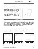
IMPORTANT: 

Make sure you lea

-

ve sufficient space around the 
rotisserie or warmer to easily 
remove or insert the rotor. If the 
base has (rotating) wheels, the 
floor on which it rests must be 
level.

LOCATION

The oven must be installed on a level surface. The installation location must allow adequate 
clearances for servicing and proper operation.

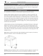
The connecting cable for the unit must be equipped with an approved plug connection. If 
use is to be made of a permanent connection, the connecting cable must be connected to a 
manual on/off switch that is installed near the unit in a clear visible manner. 

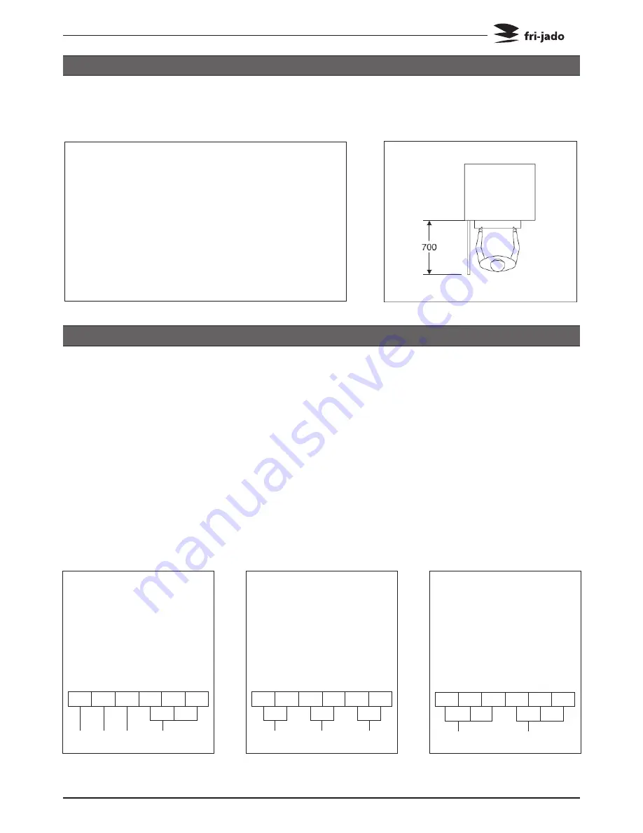
For a single-phase 200 V or 230 V ~ circuit with 
neutral, the unit must be connected according to 
the figure below.

For a 3-phase 400 V ~ circuit with neutral, the 
unit must be connected according to the figure 
below.

For a 3-phase 200 V or 230 V ~ circuit without 
neutral, the unit must be connected according to 
the figure below.

400 V, 3N ~ 50...60 Hz

200 V or 230 V, 1N ~ 50...60 Hz

200 V or 230 V, 3 ~ 50...60 Hz

Summary of Contents for TDR5 M

Page 1: ...ocedures in this manual This manual is not intended to be all encompassing If you have not at tended a training for this product you should read in its entirety the repair procedure you wish to perfor...

Page 2: ...Page 2 Installation Manual TDR5 8 form 9123825 rev 07 2010...

Page 3: ...ata 4 Installation procedures 5 Unpacking the unit 5 Location 7 Electrical supply 7 Legs Castors 8 Tethering of the unit 8 Test run 9 Extraction of the rotisserie 9 Instructions for operators 9 Placin...

Page 4: ...R 5 TDR 8 Power W 6600 10500 Fuses needed with power connec tion 400 V 3N 50 60 Hz 3 phases with zero 3x 16 A 3x 16 A Fuses needed with power connec tion 200 or 230 V 3 50 60 Hz 3 phases without zero...

Page 5: ...n his location Check if there is enough free space around the unit see installation drawing Check the electrical supply Tethering of the unit Make a test run on 250 C Give instructions to the operator...

Page 6: ...ie or warmer from a pallet is with a fork lift See pictures Open door and remove the drawer Lift the unit from pallet and put the unit in its place Note when lifting a stacked unit always use the draw...

Page 7: ...or insert the rotor If the base has rotating wheels the floor on which it rests must be level LOCATION The oven must be installed on a level surface The installation location must allow adequate clea...

Page 8: ...the building structure typically either wall or floor to limit the movement of the appliance and thus helping to prevent damage to the conduit during cleaning main tenance and service operations A te...

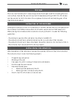
Page 9: ...ng the new oven surfaces Operate the oven at maximum temperature setting of 250 C for 30 minutes and the warmer on 100 C Smoke with an unplaesant odour will normally be given off du ring this burn in...

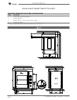
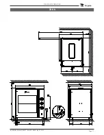
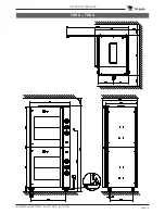
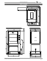
Page 10: ...belonging to the lables on the drawings Label Description 1 Power cable length 2 2 meters 2 Exhaust opening 3 Space between a rotisserie and a wall or ceiling 4 Location for socket length is measured...

Page 11: ...Page 11 Installation Manual TDR5 8 form 9123825 rev 07 2010 PLACING AND CONNECTING TDR 8...

Page 12: ...Page 12 Installation Manual TDR5 8 form 9123825 rev 07 2010 PLACING AND CONNECTING TDR 5 TDR 5...

Page 13: ...Page 13 Installation Manual TDR5 8 form 9123825 rev 07 2010 PLACING AND CONNECTING TDR 8 TDR 8...

Page 14: ...Page 14 Installation Manual TDR5 8 form 9123825 rev 07 2010 PLACING AND CONNECTING TDR 5 ON BASE...

Page 15: ...Page 15 Installation Manual TDR5 8 form 9123825 rev 07 2010 PLACING AND CONNECTING TDR 8 ON BASE...

Page 16: ...Page 16 Installation Manual TDR5 8 form 9123825 rev 07 2010 EMPTY PAGE...

Page 17: ...Installation Manual TDR5 8 form 9123825 rev 07 2010 Page 17...

Page 18: ...Fri Jado B V P O Box 560 4870 AN Etten Leur The Netherlands tel 31 76 50 85 400 fax 31 76 50 85 444 info frijado com www frijado com...

Reviews: