210.100-IOM (JUL 2018)
Page 11
ACUAIR
®
HYGIENIC AIR UNITS
INSTALLATION
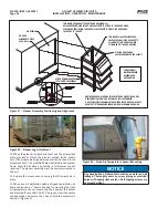
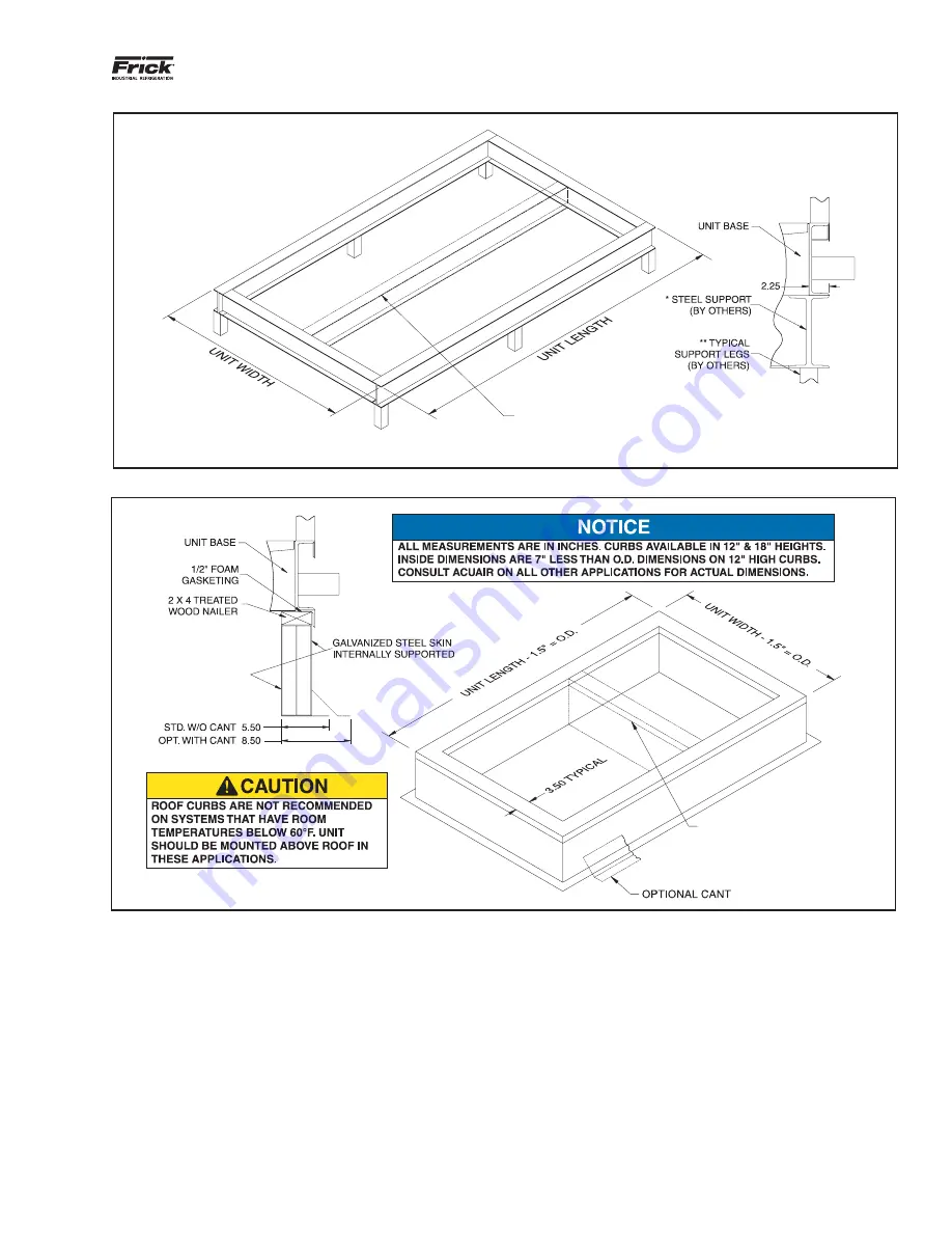
Figure 6 - Generic Structural Steel Support
ALTERNATE METHOD OF
INTERMEDIATE SUPPORT
LOCATED AT UNIT SPLIT(S)
WHEN REQUIRED
(Required on units 150" or wider)
Figure 7 - Generic Roof Curb Support
LOCATE AT CENTER OF UNIT WIDTH FOR
SUPPORT OF AIR HANDLERS 150” OR WIDER
(Optional lateral unit split supports on units 150" or wider
as represented below in Fig. 7 - Roof Curb Support.
NOTES:
1. SEE UNIT INSTALLATION DIMENSION DRAWING FOR UNIT WIDTH,
LENGTH AND WEIGHT.
2. ALTERNATE METHODS OF SUPPORT TO INCLUDE
SUPPORT AT ALL SECTION SPLITS.
* SUPPORT DESIGNED AND SUPPLIED BY OTHERS.
DRAWING FOR REFERENCE ONLY.
** LEGS TO SUPPORT THE FRAME ABOVE
THE FINISHED ROOF. NUMBER OF
LEGS AND DESIGN BY OTHERS.
SECTION RECONNECT SHIP LOOSE ITEMS
• AcuShield Roof Coating
• Joint Sealing Caulk
• Seal Gasket Tape
• 1/4" Bolts and Nuts
• Electrical Conduit Sealing Putty
INSTALLATION TOOLS
To complete the installation of an AcuAir
®
system, the
following tools are required:
• Drift Pins
• 8-Foot Straight Edge
• Level
• Assorted Open-End Wrenches
• Socket Set
• Caulk Gun
• Tape Measure
• Chain Falls
• Screw Gun with Nut Drivers
• Paint Brush or Roller for Applying AcuShield Roof Coating
Summary of Contents for AcuAir
Page 54: ......


