210.100-IOM (JUL 2018)
Page 37
ACUAIR
®
HYGIENIC AIR UNITS
OPERATION
START-UP
Before attempting to start up and operate any electrical
cooling equipment such as an AcuAir
®
system unit, it is
essential that all personnel associated with it have a basic
knowledge of how and why the unit operates in normal
conditions. The following description outlines a standard unit’s
general features, operation, and controls.
An AcuAir system (Hygienic air unit) is an engineered heat
transfer device that provides some or all of the listed functions:
cooling, dehumidification, pressurization, filtration, heating,
exhaust, and condensation control. Each unit is engineered
and designed for a specific application.
Safeties and controls vary with each AcuAir system installation
and may be interfaced with ancillary equipment or system
controls. All operators should be thoroughly trained in an
integrated cooling system’s sequence of operations and
safeties.
INITIAL START-UP
After installation of the AcuAir unit, controls and necessary
ancillary and auxiliary equipment, the entire system should
be verified before placing the hygienic system on-line for the
first time. Specifically, the following prestart measures must
be completed to ensure the readiness of the AcuAir system.
NOTICE
Do not attempt any inspection or maintenance unless
the electrical supply has been completely disconnected
and locked out.
Inspection
Do not start the unit until the following inspections verify
operational readiness. Avoid accidents or equipment failure
by rectifying any unsatisfactory condition.
• Inspect general condition of unit, e.g., structural integrity,
anchors/supports, etc.
• Confirm that all conduit openings through the walls of the
AcuAir unit, as well as conduit openings into electrical
panels, are sealed with electrical putty.
• Confirm drive assembly condition and alignment of motor,
bearings/collars, and fan/shaft.
• Confirm proper belt condition and tension. (See
Mainte-
nance
section)
• Verify there are no obstructions at the fans and fan guards.
• Verify the correct rotation of the fans.
• Understand and prepare for first 24 hour operation mea
-
sures e.g., new belt run-in procedures. (See
New Belt
Run-in
section)
• Understand and prepare the unit prestart-up checklist. See
Appendix A for the prestart-up form.
Blower, Motor, Drives
1.
Mechanical Tightness
a. Verify tightness of fan bearing bolts.
b. Verify tightness of blower wheels to shafts.
c. Verify tightness of blower, motor, and sheave.
d. Verify tightness of all motor mounting bolts.
2. Belt Tension
a. Adjust belt tension if slipping is evident.
b. Verify belt tension after 50 hours of operation and again
after 100 hours of operation.
NEW BELT RUN-IN
During initial start-up of new belts, a belt run-in procedure
is recommended. During start-up, follow these instructions:
1. Listen and look for unusual noise or vibration.
2. After shutting down and locking out the starter, check the
bearings and motor. If they feel hot, the belt tension may be
too tight.
3. Run the drive under full load for 24 hours of continuous
operation. Running the belts under full load allows them to
seat themselves into the grooves.
4. After running the drive, verify the tension of the belts.
Re-tension to the recommended values.
This run-in procedure will reduce the future need for re-
tensioning and will help extend the life of the belts.
Filters
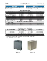
The AcuAir unit is supplied with all filter racks in place. The
filters and filter clips are shipped separately, direct from
the filter supplier. Once the unit is completely installed and
thoroughly cleaned, the
prefilters and final filters should be
installed in their respective holding frames. Once the final
filters have been installed, the final filter section and the supply
air ductwork should be cleaned and sanitized.
On units equipped with final filters, a final filter
pressure gauge
is shipped mounted. The high-pressure tube is connected to
the gauge at the factory.
The secondary port on the gauge
needs to be field routed to the ductwork downstream of the
final filters using the tubing supplied.
Cooling Coils
All refrigeration coils must be evacuated to remove moisture
prior to charging. Do not leave system or coils open and idle
prior to start-up. Internal corrosive damage can result.
Make sure piping is properly supported. Evaporators are not
designed to support external piping. Evaporator piping and
distributor tubing is not to be used for support or stepped on
during the construction process.
The use of threading compounds at coil flanges with particles
of metals (i.e. copper) embedded in the compounds can
cause corrosion due to contact of dissimilar metals. Verify
the compatibility of your construction materials with the coil
material of construction.
Refrigerant sensing devices should be employed in the
hygienic air system. These sensors should be selected and
located based on the refrigerant within the system. When
the refrigerant is ammonia, the sensors work well when
placed inside the AcuAir unit immediately downstream of
the cooling coil.
Summary of Contents for AcuAir
Page 54: ......

