VYPER
™
VARIABLE SPEED DRIVE
MAINTENANCE
100-200 IOM (FEB 09)
Page 49
MAINTENANCE
Shock Hazard! Before beginning
service, use proper lock-out/tag-out
procedures to disconnect all power
supplies related to this equipment. Verify all power is
removed from the supply leads. Death or severe personal
injury will occur if proper care is not taken.
This equipment is for power
conversion purposes. It is energized
with up to 600 volts AC and houses
a DC bus that is charged up to 1.4 times the incoming
voltage. It also encompasses multiple contactors that
may open and close without notice. It is not intended to
be operated with the doors open and appropriate ARC
FlASH protection must be used when servicing.
Shock Hazard! Wait five (5) minutes
after switching power to the Vyper
™
OFF to allow capacitors in the
cabinet to discharge before opening the cabinet
door. Failure to do so will result in death or serious
injury. After opening the door, carefully verify that the
incoming power has been removed and that the DC bus
is completely discharged with a Cat. IV meter capable of
reading up to 1000 volts AC & DC.
All service on this equipment should
be performed by Johnson Controls
-certified service personnel only.
Death, severe personal injury, and/or equipment damage
may occur if service is not performed by competent
personnel.
STANDARD MAINTENANCE
The Vyper
™
requires very little facility-operator-supplied
maintenance other than periodic torque checks on terminals.
The only maintenance item involves the coolant system. The
Vyper
™
is shipped to the customer with a premixed solu-
tion of 50/50 mixture of Propylene Glycol and a corrosion
inhibitor.
This shipping fluid needs to be replaced before starting the
unit. Although the Propylene Glycol is a food grade glycol,
proper disposal is suggested.
The standard Frick running coolant is pink in color and con-
tains a nitrite corrosion inhibitor to reduce corrosion effects
on the aluminum surfaces of the cooling circuit. The coolant
is premixed and should not be diluted. The pink color may
become clear over time. Although the color may fade, the
cooling performance remains unchanged.
The coolant should be inspected regularly and replaced an-
nually. Should it be necessary to remove the coolant for any
reason, such as equipment servicing, discard the old coolant
and replace with new coolant.
If the color of the coolant turns brown or green, this indicates
that bacteria growth is occurring If the coolant turns a milky
white color, or the inside of the tubing has a milky white coat-
ing, this indicates that the coolant is corroding the inside of
the cooling system and oxidizing the aluminum. If any of these
conditions exist, the coolant may have bacteria growth. Take
proper health precautions when draining the coolant.
• Drain the coolant and blow the system out with compressed
air.
• Flush the coolant system out thoroughly with water.
• Fill the coolant loop with
Ethylene Glycol
(Not Propylene
Glycol)
• Circulate the Ethylene Glycol for one hour.
• Drain the Ethylene Glycol and refill the coolant loop with
Frick running coolant. Please see Vyper
™
Installation Pro-
cedures section.
• Check the coolant system in two weeks for bacteria growth
and corrosion.
REPlACEMENT OF THE VYPER
™
POWER MODUlE
The following is a step-by-step procedure, which contains
several helpful hints that should make the process easier,
and minimize the possibility of damage to other components
or to the Vyper
™
drive.
Save all the packing material. This material is to be reused
when returning a defective power module as required for
warranty.
Personnel not familiar with AC drive and proper electrical
safety guidelines should not be working on this product.
Power module replacement should be performed only by
Frick certified technicians.
Power module replacement procedure:
1. Be certain the Vyper
™
has been de-energized for over five
minutes, and then double-check for presence of voltage
using a VOM. The DC bus must be fully discharged.
2. Drain the coolant from the heat exchanger into a suitable
container and discard. Use proper handling and disposal
of the coolant as it may contain bacteria.
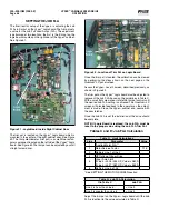
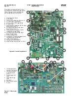
3. Remove the connector to the IGBT Gate driver board.
4. Remove and discard the (6) Phillips head screws from
the power wire connector tangs and the remaining (6)
Phillips head screws from the bus connections.
5. Remove and discard the (8) Allen screws from the IGBT
module.
6. Carefully remove the Vyper
™
power module by sliding it
away from the bus structure while lifting slightly.
DO NOT
place any stress on the bus structure! The bottom of the
IGBT module will be wet. Ensure that the coolant does
not drip onto any other components inside the Vyper
enclosure. The coolant is conductive and just one drop
on the harmonic filter gate driver can cause a failure.
7. Remove three O-rings from the copper chill plate and
discard them.
8. Wipe the chill plate clean with a clean soft cloth.
DO NOT
leave lint or any other materials on the chill plate.
DO NOT
clean using compressed air.
9. Lightly lubricate the new O-rings with O-ring lubricant
provided in the kit.
10. Install the new O-rings into the chill plate grooves
11. Place the new Vyper
™
power module on the chill plate
so the connector is towards the front of the Vyper
™
en-
closure. Carefully slide the Vyper
™
power module power
connections under the bus structure.
DO NOT
tighten.
The replacement assembly should still be loose.


