VYPER
™
VARIABLE SPEED DRIVE
INSTALLATION
100-200 IOM (FEB 09)
Page 8
The Vyper
™
can be used at altitudes up to 10,000 ft without
derating for units without the IEEE 519 Harmonic Filter. A
Vyper
™
with the Harmonic Filter included can be operated up
to 5,000 ft without derating. Due to less dense air at higher
altitudes, the maximum entering condenser water tempera-
ture, or supply cooling water, must be reduced as shown in
the following table.
Altitude
MAX Entering
Water Temp
Vyper Coolant
Control Setpoint
0 ft
100.0°F / 37.8°C
110°F / 43.3°C
5,000 ft
95.6°F / 35.5°C
105°F / 40.5°C
10,000 ft
89.6°F / 32.0°C
100°F / 37.8°C
15,000 ft
82.3°F / 27.9°C
95°F / 35.0°C
Remotely mounted units must have the distance limited
between the Vyper
™
and the compressor motor to 50 feet
of wire or less. The problems that may be encountered with
wire lengths greater than 50 are as follows;
• VSD picks up interference in the control wiring, causing
the VSD to intermittently trip.
• Voltage drop becomes excessive, rising above the 5%
voltage drop limit.
•
Peak voltage applied to the motor windings becomes
excessive and may cause premature motor failure.
• A
dV/dt filter must be installed on remote-mounted units
with motor power lead lengths between 3 to 50 feet.
Adequate service clearances, including door swing, must
be maintained around the Vyper
™
. Care should be taken to
ensure that the Vyper
™
and it’s associated piping and wiring,
do not obstruct the access to service areas.
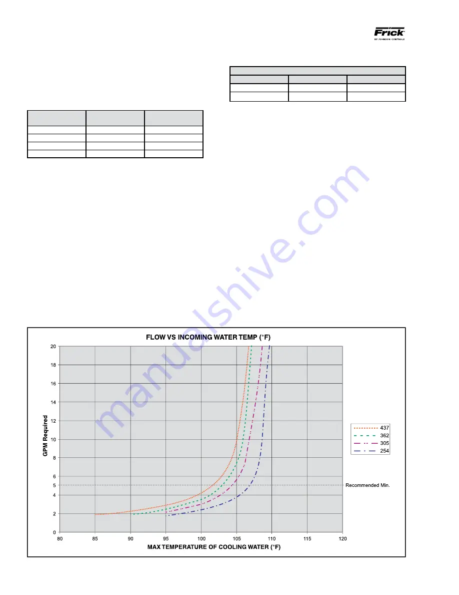
Liquid supply cooling temperature requirements vary between
Water and Glycol cooled units. The required flow rate is based
on the maximum temperature of the coolant to be used.
COOlANT TEMPERATURE lIMITS
Entering Coolant Temperature limits (Deg F)
Min
Max
Water
40
105
Glycol
35
105
General Coolant Requirements
• Vyper
™
Liquid-cooled models provide 1½ NPT threaded
connections IN and OUT of the Heat Exchanger.
• An upstream strainer is recommended to stop particulate
matter from entering the heat exchanger. The strainer
should be cleaned several times during the first twenty-four
hours of operation.
• Sufficient clearance to perform normal service and main
-
tenance work should be provided around the entire unit.
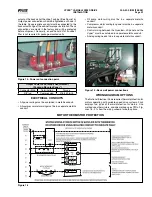
• Flow rates are as shown in the chart in Figure 2.
Water Recommendations
• Johnson Controls-Frick recommends a closed-loop system
for the water side of the heat exchanger.
• We recommend a water pH level between 6.0 and 7.4 for
proper heat exchanger life.
NOTE: To reduce the potential of fouling the heat ex-
changer, recommended minimum flow rate is 5 GPM.
Glycol Recommendations
•
Propylene Glycol is to be used exclusively. Glycol concen-
tration must be 50% or less by volume.
Figure 2 - Flow Rates


