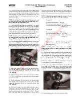
S70-101SM
Page 15
Frick XJS and XJF Rotary Screw Compressor
Service Manual
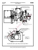
11. Remove unloader spring (22) and spring support (23).
12. Disconnect
1
/
4
-inch capacity control oil line from con-
nector located on cylinder cover (14).
13. Remove capscrews (8) securing cylinder cover to dis-
charge casing (7); remove cylinder cover and o-ring (12).
14. Using handle of a rubber mallet, push on slide valve (21)
from drive end of compressor. Slide valve piston (19) will
emerge from casing.
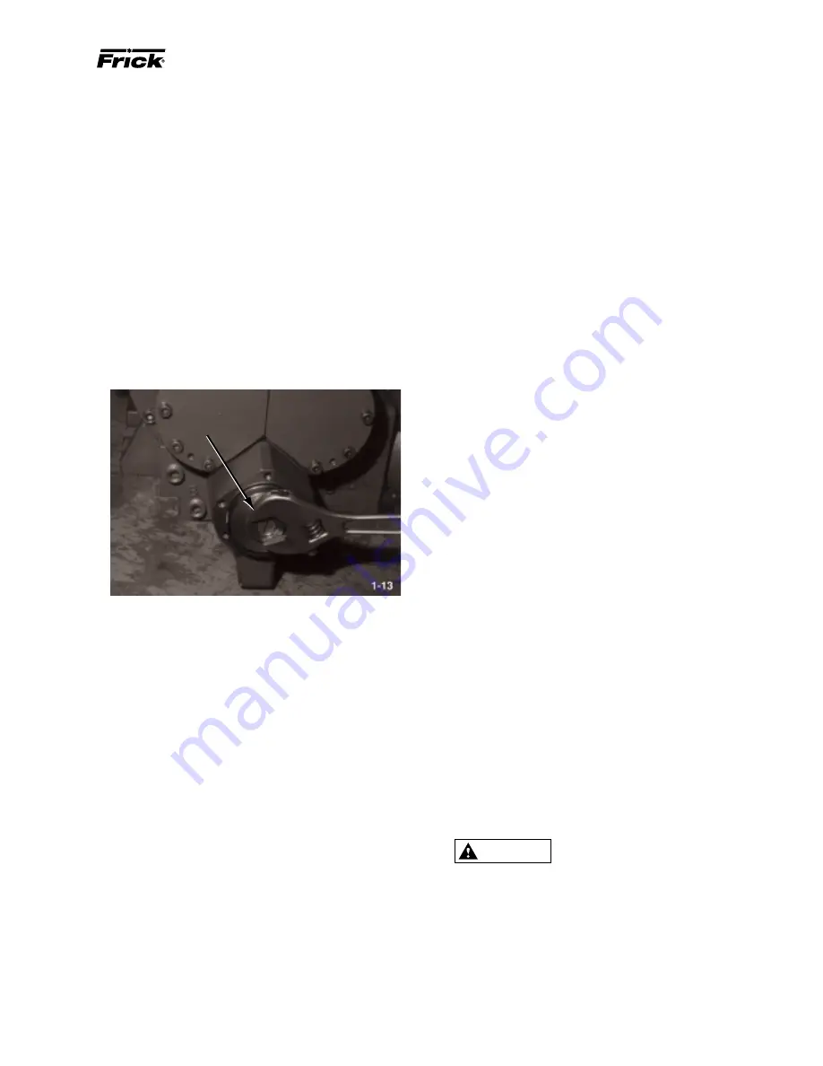
15. On older units, use a 1
1
/
4
-inch wrench to unthread slide
valve piston from slide valve; remove slide valve piston with
its glyd-rings (10 and 15) and o-ring (11). If glyd-rings and
o-ring are to be replaced, cut glyd-rings off of slide valve
piston and remove o-ring with a knife.
SLIDE VALVE PISTON
Protective, heat-resistant gloves must
be worn when installing glyd-rings.
NOTE: If glyd-rings were not removed from slide valve
piston, proceed to step 8.
4. If previously removed, install new o-ring (11) and glyd-
rings (10 and 15) on slide valve piston. To install glyd-rings,
heat to 250
×
F (121
×
C), and push into slot. Install glyd-ring
portion of the piston into piston bore for 10 minutes to ensure
glyd-ring is set.
NOTE: Newer compressors require an allen wrench to
remove M10 capscrew securing slide valve to piston. (20,
Figure 1-4)
16. Remove check valve retainer (16), internal check valve
(17), and o-ring (18) from slide valve piston (19), using a
screwdriver.
17. Push slide valve (21) out of drive end of compressor.
NOTE: If further teardown of compressor is required,
continue to paragraph 1.4.1.
1.3.2 SLIDE VALVE AND SLIDE STOP – INSTALLA-
TION.
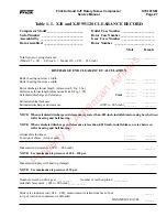
NOTE: During reassemble of the compressor it is nec-
essary to determine if the slide valve has excessive wear.
Excessive wear is defined as the slide valve being able to
move upward into the rotor bore above flush. The pro-
cedure to determine excessive movement is as follows.
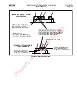
1. Insert the slide valve into the s.v. bore of the rotor hous-
ing. Without installing the rotors, install the discharge hous-
ing to the rotor housing. Secure the discharge housing with
two cap screws and insert dowel pins.
2. By inserting your hands through the suction ports, move
the s.v. into the discharge port so that the s.v. guides
are securing the s.v. in place.
3. Push against the side of the slide valve with one hand and
by using either a thin feeler gauge or fingernail, determine if
the slide valve moves into the rotor bore. The slide valve
should not rise above the bore.
If the slide valve does move into the rotor bore, it may be
necessary to replace either the slide valve, the discharge hous-
ing, or both. Because the slide valve guides on the discharge
housing are machined oversized , the slide valve must be hand
fitted to the discharge housing. Use the following procedure
when new parts are required.
1. Install the slide valve in the rotor housing. Without install-
ing the rotors, install the discharge housing with two
capscrews and dowel pins.
2. After inserting your hands through the suction ports, move
the slide valve into the discharge housing. The slide valve
will get tight within the guides. Pull the slide valve completely
out of the discharge port. Using sand paper, lightly sand the
slide valve guides on the discharge housing. The process of
sanding the guides must be done with care. Ensure that the
sanding is conducted evenly across the guides and remove
only a small amount of material before checking the fit. If
excessive material is removed from the guides, the slide valve
will move into the rotor bore.
3. The slide valve is correctly fitted when it is able to move
smoothly in and out of the guides a~ without moving into the
rotor bore.
Slide valve and slide stop installation shall be accomplished as
follows:
NOTE: Index numbers refer to Figure 1-4, unless other-
wise noted.
1. Thoroughly clean all parts with OSHA approved, nonflam-
mable degreaser and clean, lint-free rags.
2. Lubricate all internal compressor parts with a coat of clean
refrigerant oil.
3. Install slide valve (21) into drive end of compressor.
WARNING
Property of American Airlines


