S70-101SM
Page 18
Frick XJS and XJF Rotary Screw Compressor
Service Manual
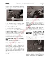
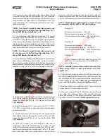
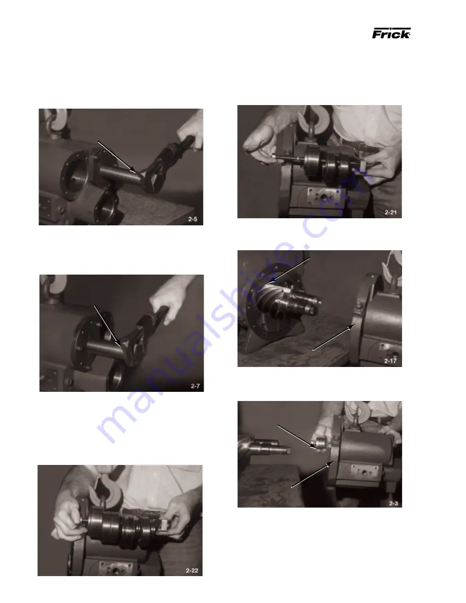
12. Install Discharge Ball Bearing Removal Tool on nondrive
end of male rotor shaft. Turn jacking screw clockwise to
remove four-point contact ball bearing (34) and angle con-
tact ball bearings (26) off of shaft, as discharge casing
separates from rotor casing (3)
JACKING SCREW
(DISCHARGE BALL BEARING
REMOVAL TOOL)
NON-DRIVE END
MALE ROTOR SHAFT
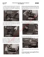
MALE DISCHARGE BEARING
AND BALANCE PISTON GROUP
14. Remove four-point contact ball bearing (34), balance
piston (33), wave spring (31), bearing spacer (32), balance
piston sleeve (30), angular contact bearings (26), and shims,
if used, from male rotor bore in discharge casing. Label any
shims to permit reinstallation in correct bore. Remove o-rings
(27 and 29) from balance piston and balance piston sleeve.
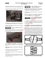
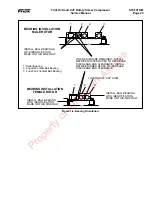
13. Install Discharge Ball Bearing Removal Tool on nondrive
end of female rotor shaft. Turn jacking screw clockwise to
remove angular contact ball bearings from shaft. When jack-
ing screw bottoms, remove tool..
NON-DRIVE END
FEMALE ROTOR SHAFT
JACKING SCREW
(DISCHARGE BALL BEARING
REMOVAL TOOL)
FEMALE DISCHARGE
BEARING GROUP
15. Remove angle contact ball bearings and shim, if used,
from female rotor bore in discharge casing. Label any shims
to permit reinstallation in correct bore. If ball bearings and
balance piston (male side) are unable to be removed, they can
be removed in step #17.
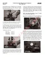
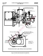
16. Pull discharge casing away from rotor casing, using care
so as not to damage ends of rotor shafts (47).
18. Remove two gas seals (24) and o-rings (23) from discharge
casing.
19. Remove male rotor from rotor casing. Rotor will have to
be turned while pulling it out of casing. Place rotor on
cardboard or wooden surface.
ROTOR CASING
DISCHARGE CASING
DISCHARGE CASING
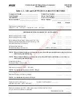
DISCHARGE BEARING
PULLER
17. Using Discharge Roller Bearing Puller, remove two roller
bearings (25) from discharge casing.
Property of American Airlines


