S70-101SM
Page 27
Frick XJS and XJF Rotary Screw Compressor
Service Manual
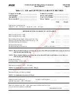
Table 1-1. XJS and XJF 95/120 CLEARANCE RECORD
Male Female
Total rotor-to-casing clearance:
________ ________
(Model 95 ± .021 – .027-inch • Model 120 ± .025 – .031-inch)
Compressor Model ______________________
Serial Number _________________________
Assembled by __________________________
Date Assembled ________________________
Outlet Case Number ____________________
Rotor Case Number _____________________
Gear Cover Number ____________________
Rotor Number _________________________
DISCHARGE END CLEARANCE CALCULATION
Roller bearing outer race width
________ ________
Roller bearing inner race width
________ ________
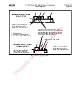
Rotor discharge throat length (dimension 8, Fig. 1-5a)
________ ________
Outlet case throat length (dimensions R & S, Fig. 1-5b)
– ________ – ________
Calculated discharge end clearance
Total ________ ________
Estimated shim thickness
________ ________
Estimated discharge end clearance
(.0015 to .003-inch) ________ ________
NOTE: When calculated discharge end clearance is greater than .003-inch, install shims in casing bore between
roller bearing and ball bearing.
NOTE: When calculated discharge end clearance is less than .0015-inch, install shims on rotor between
roller bearing and ball bearing.
Actual shim thickness
________ ________
Location of shims (rotor or case)
________ ________
Measured end clearance (.0015 – .003-inch)
________ ________
NOTE: Use maximum air pressure of 100 – 120 psi.
Measured end play with bearing clamped
________ ________
NOTE: Use maximum air pressure of 35 psi.
Number of teeth on drive gear __________ Number of teeth on pinion __________
Jackshaft movement (.001 to .005-inch) __________
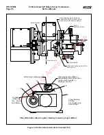
Slide valve indicator rod (.044 – .084); measurement is taken from face of nut
_______
to tip of rod when compressor is unloaded.
MAXIMUM TRAVEL _______
Property of American Airlines


