


PA3200C
23
EN
General Instructions
Read these instructions carefully prior to
installation and use. Keep this manual for
future reference.
The product may only be used as set out in
the assembly and operating instructions. The
guarantee is only valid should the product
be used in the manner intended and in
accordance with the instructions.
Application
PA3200C is a compact air curtain with a
recommended installation height of 3,2
metres. The air curtain has an integrated
control system and can be remotely
controlled.
The air curtain is available without heat,
with electrical heating and with water heating.
Protection class for units with electrical
heating: IP20.
Protection class for units without heating and
units with water heating: IP21.
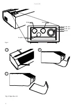
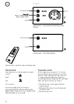
Operation
Air is drawn in at the top of the unit and
blown downwards shielding the door opening
and minimizing heat loss. To achieve the
optimum curtain effect the unit must extend
the full width of the door opening.
The grille for directing the outlet air is
adjustable and is normally angled outwards to
achieve the best protection against incoming
air.
The efficiency of the air curtain depends on
the air temperature, the pressure differencial
across the doorway and any wind load.
NOTE! Negative pressure in the building
considerably reduces the efficiency of the air
curtain. The ventilation should therefore be
balanced.
Mounting
The air curtain is installed horizontally with
the outlet air grille facing downwards as close
to the door as possible. The product must be
mounted in such a way to allow future service
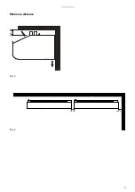
and maintenance. Minimum distance from
outlet to floor for electrically heated units is
1800 mm. For other minimum distances, see
fig. 4.
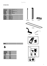
Brackets and torx bit are enclosed in the
gable end packaging upon delivery.
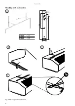
Mounting with wall brackets (fig. 6)
1. Mount the brackets on the wall, see fig.6A
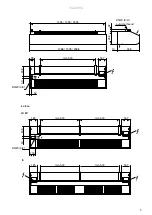
and dimension drawing fig.1. If the wall is
uneven the brackets must be compensated
for this.
2. Hook on the unit at the lower edge of the
brackets. (Fig.6B)
3. Bend the top of the console over the the
unit and slide the units screws along the
rail into the slots on the consoles. (Fig.6C)
When the bracket is bent once, it must be
replaced if bent back more than 45 °.
4. Lock the nuts against the brackets. (Fig.6D)
Horizontal mounting on the ceiling
Threaded rods, hanging brackets and ceiling
mounting brackets for ceiling mounting are
available as accessories, see accessories pages
and separate manuals.
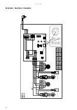
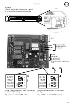
Electrical installation
The installation, which should be preceded by
an isolator switch with a contact separation
of at least 3 mm, should only be wired by a
competent electrician and in accordance with
the latest edition of IEE wiring regulations.
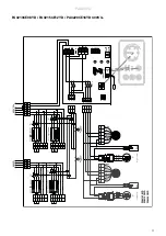
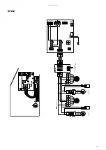
The control system is pre-installed in the air
curtain.
Unit without heating
Connected via the built-in control board with
1,5 m cord and plug.
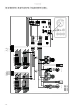
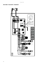
Unit with water heating
Connected via the built-in control board with
1,5 m cord and plug.
Installation and operating instructions
Summary of Contents for 19802
Page 5: ...PA3200C 5 Fig 4 Fig 5 Minimum distance 30 mm 60 mm min 60 ...
Page 22: ......


