


PA3200C
24
EN
Service, repairs and maintenance
For all service, repair and maintenance first
carry out the following:
1. Disconnect the power supply.
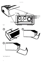
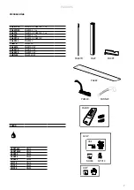
2. The front hatch is removed by removing
the screws on the top of the unit and then
detach the bent edge at the bottom. (Fig.3)
3. After the service, repair and maintenance
reattach the front hatch. Place the hatch
at the lower edge with the bent edge and
fasten on top with screws.
Note that when carrying out work where the
end is removed, the outlet grille also detaches.
Start-up (E)
When the unit is used for the first time or
after a long period of non-use, smoke or an
odour may result from dust or dirt which has
collected on the element. This is completely
normal and disappears after a short time.
Adjustment of the air curtain and airflow
The direction and speed of the airflow should
be adjusted considering the load on the
opening. Pressure forces affect the airstream
and force it inwards towards the premises
(when the premises are heated and the
outdoor air is cold).
The airstream should, therefore, be directed
outwards to withstand the load. Generally
speaking, the higher the load, the greater the
angle required.
Basic setting fan speed
The fan speed when the door is open is
set using the control. Note that the airflow
direction and the fan speed may need fine
adjustment depending on the loading of the
door.
Filter (W)
The water coil is protected against dirt and
blockage by an internal air filter which covers
the coil face. In environments where the filter
requires frequent cleaning, it is advisable to
use an external intake filter (see accessories
pages), which provides easier maintenance,
since the unit does not need to be opened.
When an external filter is used, the internal
filter is removed.
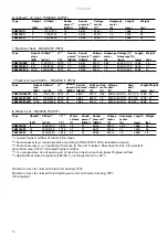
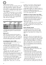
[kW]
[V]
[mm
2
]
0
230V~
1,5
PA3210CE08
8
400V3~
2,5
PA3215CE12
12
400V3~
4
PA3220CE16
16
400V3~
6
*) Dimensioning of external wiring shall comply
with applicable regulations and local deviations
may occur.
Type
Output
Voltage
Minimum
area*
Control
Connecting the water coil (W)
The installation must be carried out by an
authorised installer.
The water coil has copper tubes with
aluminium fins and is suitable for connection
to a closed water heating system. The heating
coil must not be connected to a mains
pressure water system or an open water
system.
Note that the unit shall be preceded by a
regulating valve, see Frico valve kit.
The water coil is connected on top of the unit
via steel pipes with DN20 (3/4’’) terminals,
external thread. Flexible hoses are available
as accessories, see accessories pages.
The connections to the heating coil must
be equipped with shut off valves to allow
trouble-free removal. The water coil is
equipped with a drain valve. A vent valve
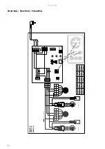
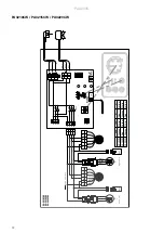
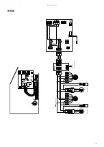
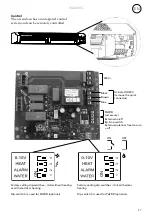
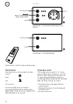
Unit with electrical heating
The electrical connection is made on the top
of the unit. See Fig.2. Control (230V~) and
power supply for heat (400V3~) should be
connected to a terminal block in the terminal
box. 2-metre and longer units require dual
power supplies.
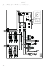
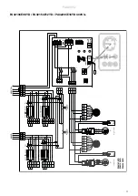
The largest cable diameter for the terminal
block is 16 mm². The cable glands used must
meet the protection class requirements. In
the distribution board, it is to be indicated
that ”the air curtains can be supplied from
more than one connection”.
See wiring diagrams.
should be connected at a high point in the
pipe system. Air valves are not included.
NOTE: Care must be taken when
connecting the pipes. Use a pipe wrench or a
similar tool to grip the air curtain connections
to prevent straining of the pipes and
subsequent water leakage during connection
to the water supply pipe-work.
Summary of Contents for 19802
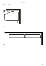
Page 5: ...PA3200C 5 Fig 4 Fig 5 Minimum distance 30 mm 60 mm min 60 ...
Page 22: ......


