
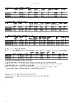
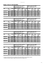


PA3200C
27
EN
1
2
3
4
ON
1
2
3
4
ON
230V~
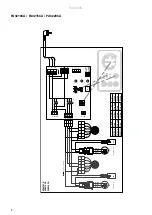
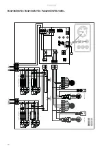
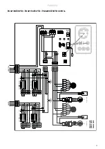
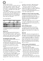
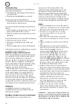
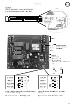
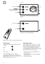
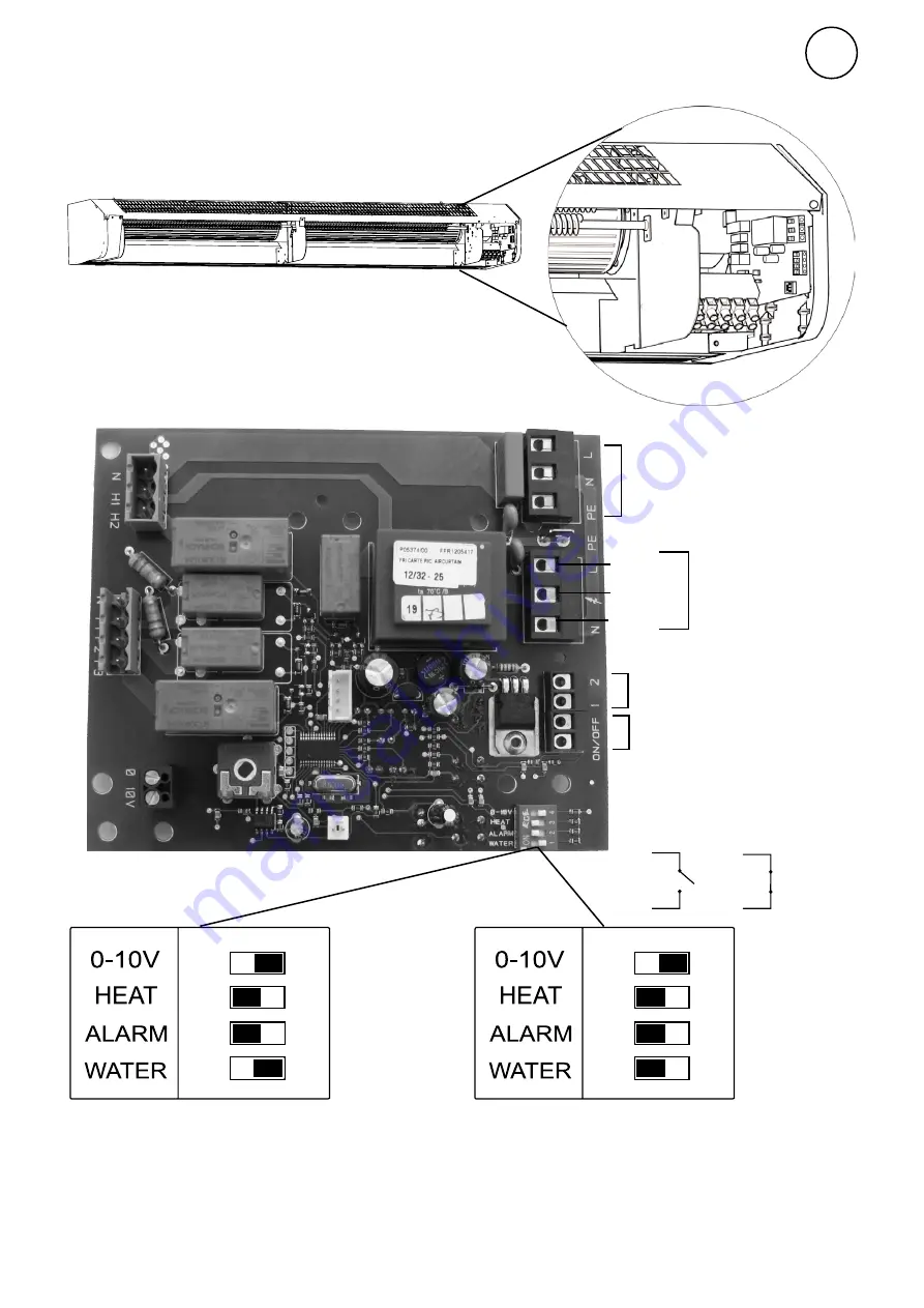
Control
The air curtain has an integrated control
system and can be remotely controlled.
ON
OFF
Actuator SD230
(remove the quick
connector)
Black
Brown
Blue
External on/off
Eg time switch.
External potential free closure
= off
PA2DR
(accessory)
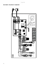
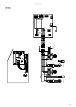
Factory setting dip-switches - Unit with water
heating
Dip-switch 3 is used for PA2DR (optional).
2
1
3
Factory setting dip-switches - Unit without heating
or with electrical heating
Dip-switch 3 is used for PA2DR (optional).
Summary of Contents for 19802
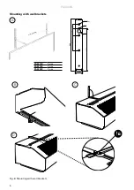
Page 5: ...PA3200C 5 Fig 4 Fig 5 Minimum distance 30 mm 60 mm min 60 ...
Page 22: ......