background image

PA3200C

8

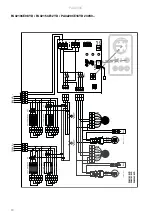
PA3210CA / PA3215CA / PA3220CA

5A x 

3

N H1H2

N

1

On

Off

F1 F2 F3

on/off

2

N

L

PE

N

L

PE

~

0 -10V

0 - 

10

V

HEA

T

ALARM WA

TE

R

IR

PA321

0CA

PA3215CA

PA3220CA

3220C

A

3215C

A

3210C

A

Red

Red

Black

Blue

Brown

L

N

Low
Mi

d

b1

c1

Orange

Yellow

Yellow

Yellow

Mi

d

Low

Blue

Black

b1

c1

Orang

e

Red

Orang

e

White

White

White

Black

Blue

Brown

M

Le

ft

 motor

~

Ru

n

Only 2 m ver

sion

Black
Blue

Low

L

N

Mi

d

c1

b1

M

Right motor

~

Ru

n

Summary of Contents for 19802

Page 1: ...PA3200C 16 SE 23 GB Original instructions 29 NO 36 DE 44 ES 52 FR 60 IT 68 NL 77 PL 84 RU 92 FI 99 DK ...

Page 2: ...básicamente imágenes Consulte la traducción de los textos en inglés que las acompañan en las páginas del idioma correspondiente ES De inleidende pagina s bevatten hoofdzakelijk afbeeldingen Voor een vertaling van de gebruikte Engelse teksten zie de pagina s van de resp taal NL Le pagine introduttive contengono prevalentemente immagini Per le traduzioni dei testi scritti in inglese vedere le pagine...

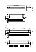
Page 3: ...00 165 209 50 min 500 min 500 167 165 119 DN20 3 4 1045 1555 2045 1068 1578 2068 42 256 10 458 167 min 500 99 209 50 52 DN20 3 4 167 min 500 min 500 165 209 50 min 500 min 500 167 165 119 DN20 3 4 1045 1555 2045 1068 1578 2068 42 256 10 458 167 min 500 99 209 50 52 DN20 3 4 167 min 500 min 500 165 209 50 min 500 min 500 167 165 119 DN20 3 4 ...

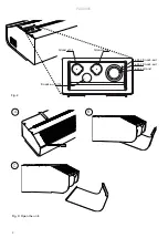
Page 4: ...PA3200C 4 Fig 2 Fig 3 Open the unit A B C Gland Knock out Knock out Knock out ø17 5 ø17 5 ø32 5 ø25 5 ø20 5 ø17 5 Gland Gland ...

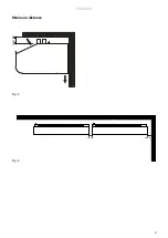
Page 5: ...PA3200C 5 Fig 4 Fig 5 Minimum distance 30 mm 60 mm min 60 ...

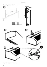
Page 6: ...PA3200C 6 min 500 mm Fig 6 Mounting with wall brackets Mounting with wall brackets PA3210C 2 pcs PA3215C 2 pcs PA3220C 3 pcs A B C D Ø8 3x Ø7 Ø16 213 37 260 75 35 20 ...

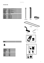
Page 7: ...3220C 1 m PA3PF15 PA3210C PA3215C PA3PF20 PA3220C PAMLK PA3200C PA3EF10 PA3210C W PA3EF15 PA3215C W PA3EF20 PA3220C W FHDN20 PA3200C W PA2DR PA34TR PA2P PA3PF PA2DR PAMLK FHDN20 AUTO PA3EF VKF SD230 BPV10 VLSP VOT VLSP15LF DN15 VLSP15NF DN15 VLSP20 DN20 VLSP25 DN25 VLSP32 DN32 VOT15 DN15 VOT20 DN20 VOT25 DN25 ...

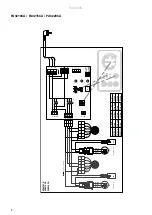
Page 8: ...0V HEAT ALARM WATER IR PA3210CA PA3215CA PA3220CA C 3220CA 3215CA 3210CA Red Red Black Blue Brown L N Low Mid b1 c1 Orange Yellow Yellow Yellow Mid Low Blue Black b1 c1 Orange Red Orange White White White C Black Blue Brown M Left motor Run Only 2 m version Black Blue Low L N Mid c1 b1 M Right motor Run ...

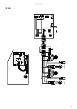
Page 9: ...t cut out C K1 K1 high power K2 low power L2 PE L1 L N L3 400V 3N Over heat C cut out PA3210CE PA3215CE PA3220CE Only 2 m version K4 K3 K3 high power K4 low power PE 400V3 L2 L1 L3 C Black Brown Blue Mid Low N L c1 b1 Red Yellow Orange White Blue Black C M Left motor Run M Right motor Run Black Blue Brown N b1 c1 Mid L Low Red Yellow Orange Black Blue White ...

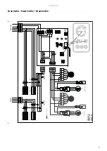
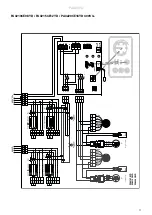
Page 10: ...0V 3 5A x 3 N H1H2 N 1 On Off F1 F2 F3 on off 2 N L PE N L PE 0 10V 0 10V DOOR AFTER WATER INTERNAL SENSOR IR Over heat cut out C Over heat cut out C Brown C Blue Black Mid N L Low b1 c1 Orange White Black Blue Red Yellow C Orange White Black Blue Yellow Red b1 N L Low Mid c1 Brown Blue Black M Left motor M Right motor Run Run ...

Page 11: ...00V3 5A x 3 N H1H2 N 1 On Off F1 F2 F3 on off 2 N L PE N L PE 0 10V 0 10V DOOR AFTER WATER INTERNAL SENSOR IR Over heat cut out C Over heat cut out C Brown Black C Blue Low N Mid L b1 c1 Red Blue Black Orange White Yellow Brown C Blue Black M Left motor M Right motor Run Run Black Blue Orange White Red Yellow N Low L Mid b1 c1 ...

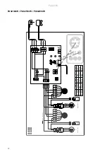
Page 12: ...TER INTERNAL SENSOR IR PA3210CW PA3215CW PA3220CW Black Brown Blue C 3220CW 3215CW 3210CW Red Black Blue Brown L N Low Mid b1 c1 Orange Orange White Yellow White Mid Low Blue Black b1 c1 Red Orange Red Yellow White Yellow C Black Blue Brown M Left motor Run Only 2 m version Black Blue Low L N Mid c1 b1 M Right motor Run ...

Page 13: ... alarm pot free contact 5A x 3 5A 16A N H1H2 N 1 On Off F1 F2 F3 on off 2 N L PE N L PE 0 10V 0 10V HEAT ALARM WATER INTERNAL SENSOR IR C C Black Brown Blue Mid Low N L c1 b1 C M Left motor Run M Right motor Run Black Blue Brown N b1 c1 Mid L Low Only 2 m version ...

Page 14: ...230V3 400V3 30 1 17 3 1578 37 PA3220CE16YD 10 16 2300 3500 22 13 76 50 60 230V 1 3 230V3 400V3 40 2 23 1 2068 51 Type Output 5 kW Airflow 1 m3 h t 4 5 C Water volume l Sound power 2 dB A Sound pressure 3 dB A Voltage motor V Amperage motor A Length mm Weight kg PA3210CW 8 1050 1700 16 14 1 3 70 45 55 230V 0 65 1068 26 PA3215CW 14 1850 2700 17 15 2 1 73 46 57 230V 0 7 1578 36 PA3220CW 18 2200 3300 ...

Page 15: ...PA3215CW max 2700 16 0 45 0 26 13 4 13 9 33 0 17 6 3 min 1850 10 8 40 0 13 4 0 10 8 35 0 13 4 0 PA3220CW max 3300 18 9 42 0 26 10 2 17 6 34 0 21 7 1 min 2200 12 9 39 0 15 3 6 13 4 36 0 16 4 4 Supply water temperature 55 C Room temperature 18 C Outlet air temperature 35 C 1 Water temperature 55 35 C Room temperature 18 C Type Fan position Airflow m3 h Output kW Return water temp C Water flow l s Pr...

Page 16: ...ir curtain is installed horizontally with the outlet air grille facing downwards as close to the door as possible The product must be mounted in such a way to allow future service and maintenance Minimum distance from outlet to floor for electrically heated units is 1800 mm For other minimum distances see fig 4 Brackets and torx bit are enclosed in the gable end packaging upon delivery Mounting wi...

Page 17: ...need to be opened When an external filter is used the internal filter is removed kW V mm2 0 230V 1 5 PA3210CE08 8 400V3 2 5 PA3215CE12 12 400V3 4 PA3220CE16 16 400V3 6 Dimensioning of external wiring shall comply with applicable regulations and local deviations may occur Type Output Voltage Minimum area Control Connecting the water coil W The installation must be carried out by an authorised insta...

Page 18: ...astic ends 4 Detach the intake grille by drilling out the rivet s 5 Remove the mounting screws securing the coil in the unit and lift out 6 Install the new coil in reverse order to the above Replacing motor or impeller 1 Remove the front 2 Remove gable end 3 Remove the screw between motor and fan 4 Disconnect the cables to the motor 5 Remove the screws securing the motor and lift it out together w...

Page 19: ...king life This product may contain substances necessary for the functionality of the product but potentially dangerous for the environment The product should not be disposed of mixed with general household waste but delivered to a designated collection point for environmental recycling Please contact the local authority for further details of your nearest designated collection point Safety For all...

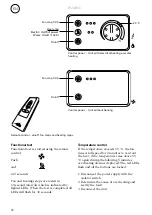
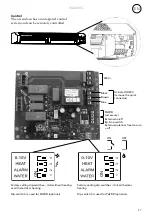
Page 20: ...D230 remove the quick connector Black Brown Blue External on off Eg time switch External potential free closure off PA2DR accessory Factory setting dip switches Unit with water heating Dip switch 3 is used for PA2DR optional 2 1 3 Factory setting dip switches Unit without heating or with electrical heating Dip switch 3 is used for PA2DR optional ...

Page 21: ...utes to vent out the heat if the temperature rises above 50 C again during the following 5 minutes overheating alarm is deployed The red LEDs flash and all the buttons are locked 1 Disconnect the power supply with the isolator switch 2 Determine the cause of overheating and rectify the fault 3 Reconnect the unit Functional test Functional test is started using the remote control Push and in 5 seco...

Page 22: ......
Page 23: ...Art no 117958 2020 10 09 HH CH ...

Reviews: