Thermocassette HP
9
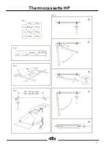
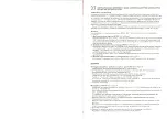
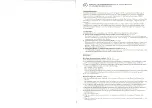
Wire hung. See fig.5.
1 . Mounting height above floor shall be 1.8 m,
and lateral distance to wall at least 50 mm.
2 . Installation, which is to be preceded by an all-
pole switch, must be carried out by an
authorized electrician (not applicable to version
with a cord).
3 . Measure, drill and screw in the wire
attachments envloesed in
”Wire mounting kit” 74 701 90 to the ceiling
4 . Insert one wire end in each screw hole in the
bracket ends on the panel, and fix with a screw
terminal
5 . Hang up the panel bt hanging one wire on the
screw in each wire attachment in the ceiling.
Tighten the screws.
6 . Connect the panel.
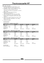
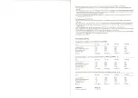
Technical Data
Ceiling model - standard version IP20
Typ
HP-300
HP-300
HP-600
HP-600
Power (W)
300
300
600
600
Voltage (V)
230
400
230
400
Current (A)
1,30
0,75
2,61
1,50
Weight (kg)
5,4
5,3
10,3
10,2
Order nr.
84 030 21
84 030 31
84 060 21
84 060 31
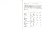
Universal model - waterproof version IP54
Typ
HP-304
HP-304
HP-604
HP-604
Power (W)
300
300
600
600
Voltage (V)
230
400
230
400
Current (A)
1,30
0,75
2,61
1,50
Weight (kg)
5,9
5,8
10,8
10,7
Order nr.
84 034 21
84 034 31
84 064 21
84 064 31
Universal model - waterproof version IP55
Typ
HP-305
HP-305
HP-605
HP605
Power (W)
300
300
600
600
Volatage (V) 230
400
230
400
Current (A)
1,30
0,75
2,61
1,50
Weight (kg)
5,8
5,8
10,7
10,7
Order nr.
84 035 21
84 035 31
84 065 21
84 065 31
Accessories
E- nr.
Order nr.
Wire mounting kit
85 744 90
74 701 90
Summary of Contents for Thermocassette HP300
Page 1: ...Thermocassette HP SE 4 GB 8 NO 6 DE 10 ...
Page 2: ...Thermocassette HP 2 ...
Page 3: ...Thermocassette HP 3 ...
Page 6: ......
Page 7: ......
Page 8: ......
Page 9: ......
Page 10: ......
Page 11: ......


