20
PB
SPECIFICATIONS
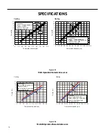
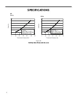
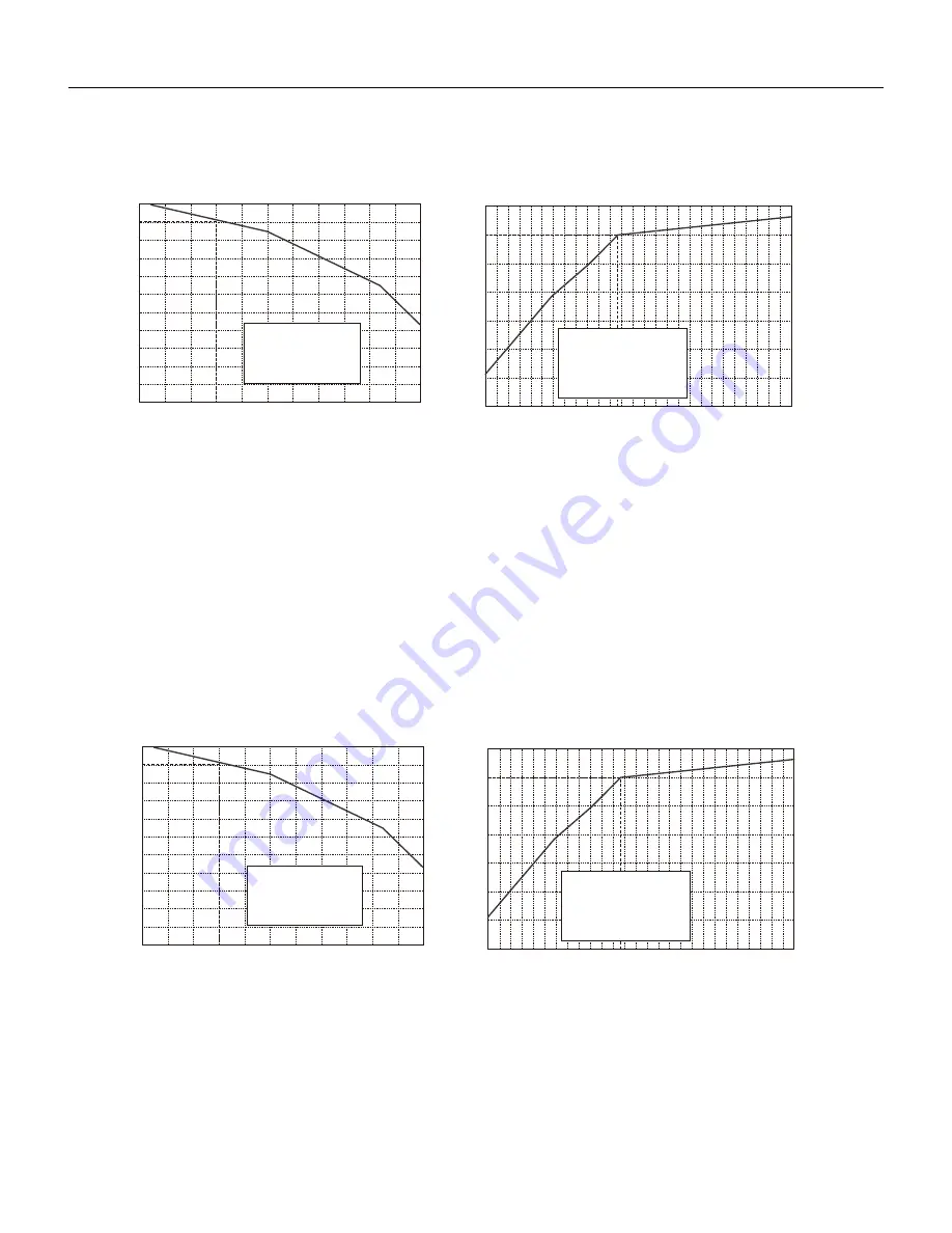
Figure 206
9-12K Capacity Variation Ratio According to Temperature
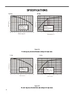
Figure 207
18-24 K Capacity Variation Ratio According to Temperature
Cooling
Heating
5
-4
4
1
110
100
90
80
70
60
50
40
23
32
41
50
Outdoor temp.(°F)
Capacity ratio (
%
)
100
105
95
90
85
80
75
70
65
89.6 91.4 93.2
95 96.8 98.6 100.4 102.2 104 105.8 107.6 109.4
60
55
50
Outdoor temp.(°F)
Capacity ratio (
%
)
Conditions
Outdoor:DB95°F
flow:Super High
Indoor air
Indoor:DB
80°F
/WB66.9
°F
Pipe length:
24.6ft
Conditions
Outdoor:DB19.94°F/WB19.04°F
Indoor:DB
70°F
air flow:Super
Indoor
High
Pipe length:
24.6ft
Cooling
-4
5
4
1
110
100
90
80
70
60
50
40
23
32
41
50
Outdoor temp.(°F)
Capacity ratio (
%
)
100
105
95
90
85
80
75
70
65
60
55
50
Capacity ratio (
%
)
Outdoor:DB95°F
Indoor air flow:Super High
Conditions
Indoor:DB
80°F
/WB66.9
°F
89.6 91.4 93.2
95 96.8 98.6 100.4 102.2 104 105.8 107.6 109.4
Outdoor temp.(°F)
Pipe length:
24.6ft
Conditions
Indoor:DB
70°F
Outdoor:DB19.94°F/WB19.04°F
Indoor air flow:Super High
Pipe length:
24.6ft
Heating
Summary of Contents for FSHW091
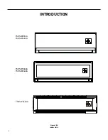
Page 8: ...8 INTRODUCTION FSHSW09A1A FSHSW12A1A Figure 102 Indoor Units FSHSW18A3A FSHSW24A3A FSHSW36A3A ...
Page 47: ...47 INSTALLATION ...
Page 48: ...48 INSTALLATION Installation Tools ...
Page 72: ...72 WIRED CONTROLLER Display ...
Page 122: ...122 TROUBLESHOOTING Malfunction of IDUFanMotorU8 Service Manual No Start End ...
Page 146: ...146 WIRING DIAGRAMS Figure 8054 9 12KOutdoorUnitWiringDiagrams 60000706067401 3 2 N 1 C3 C4 ...
Page 158: ...158 FIgure 906 PARTS CATALOG 9KOutdoorUnit 28 27 29 31 30 32 ...
Page 160: ...160 PARTS CATALOG 12k OutdoorUnit 28 27 29 31 30 32 FIgure 907 ...

