86
PB
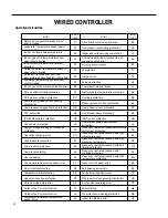
Error
Error
Code
Error
Error
Code
Communication error between IDU and
grid connection
Communication error between ODU and
grid connection
Main error at grid connection side
IDU network address error
Ip address allocation overflow
Ln
LM
y2
y3
yb
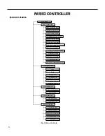
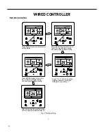
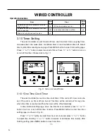
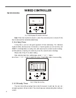
3.10 Timer Setting
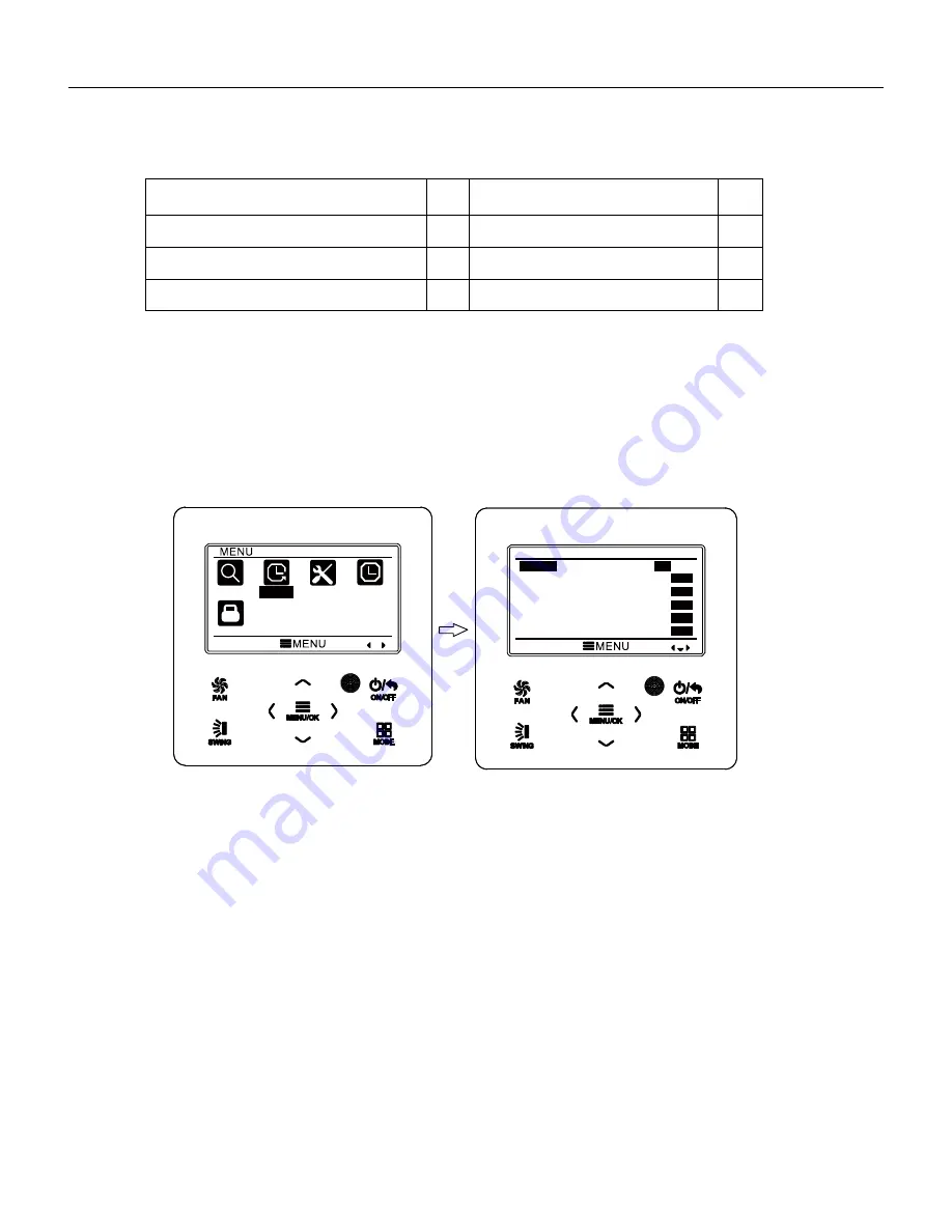
The wired controller can set 6 kinds of timer: one time clock timer, everyday timer,
one week timer, two week timer, countdown timer on and countdown timer off. Select
timer symbol after entering menu page. Press MENU button to enter timer setting page.
Press “
∧
” or “
∨
” button to select one kind of timer. Press “
<
” or “
>
” button to turn on
or turn off this timer. Please refer to Fig. 11.
Fig. 11 Turn on or turn off timer
3.10.1 One Time Clock Timer
The wired controller can set one time clock timer. If the unit is off, timer on can be
set. If the unit is on, timer off can be set. This timer will be carried out for only once
when timer time is reached and then the timer will be off automatically.
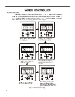
In timer function setting page, when one time timer is selected, press “
<
” or “
>
”
button to turn on or turn off this timer function. Press MENU button to enter timer time
setting page, as shown in Fig. 12.
Press “
<
” or “
>
” button to select timer hour or minute and press “
∧
” or “
∨
” button
to adjust time. Holding “
∧
” or “
∨
” button increases or decreases time rapidly. After
finishing setting, press MENU button to save timer time.
Wired Controller
FSWC1
Owner's Manual
15
SEARCH
TIMER
FUNCTION CLOCK
LOCK
TIMER
ONCE
ON
OFF
ON
OFF
ON
OFF
DAILY
WEEKLY
TWO WEEK
TIMER ON
TIMER OFF
ON
OFF
ON
OFF
ON
OFF
WIRED CONTROLLER
Operation Instructions
Summary of Contents for FSHW091
Page 8: ...8 INTRODUCTION FSHSW09A1A FSHSW12A1A Figure 102 Indoor Units FSHSW18A3A FSHSW24A3A FSHSW36A3A ...
Page 47: ...47 INSTALLATION ...
Page 48: ...48 INSTALLATION Installation Tools ...
Page 72: ...72 WIRED CONTROLLER Display ...
Page 122: ...122 TROUBLESHOOTING Malfunction of IDUFanMotorU8 Service Manual No Start End ...
Page 146: ...146 WIRING DIAGRAMS Figure 8054 9 12KOutdoorUnitWiringDiagrams 60000706067401 3 2 N 1 C3 C4 ...
Page 158: ...158 FIgure 906 PARTS CATALOG 9KOutdoorUnit 28 27 29 31 30 32 ...
Page 160: ...160 PARTS CATALOG 12k OutdoorUnit 28 27 29 31 30 32 FIgure 907 ...


