


1
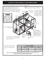
ELECTRIC COOKTOP INSTALLATION INSTRUCTIONS
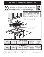
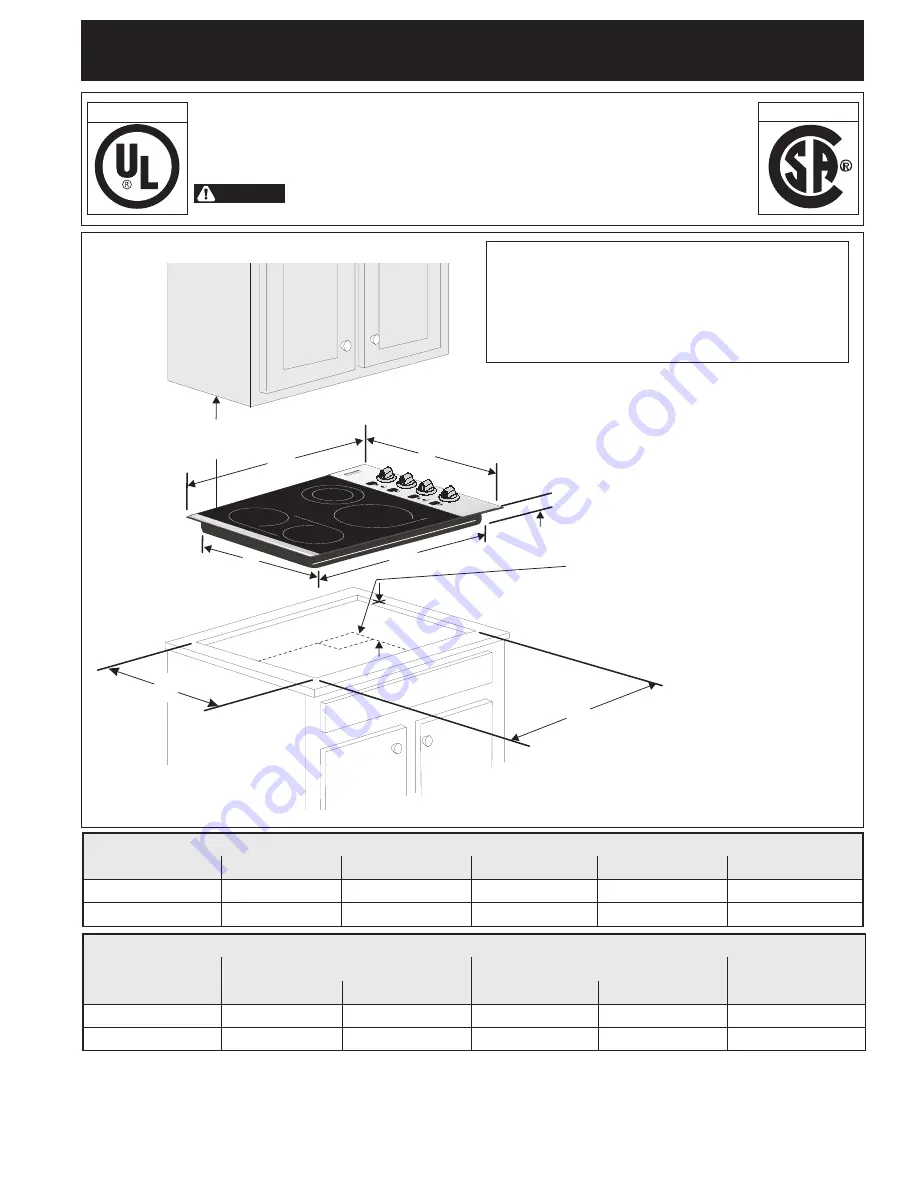
A
H
B
C
F
G
30” Min. *
(76.2 cm)
D
E
Cooktop Dimensions
IMPORTANT INSTALLATION‑INFORMATION
• All electric cooktops run off a single phase, three-wire
or four-wire cable, 240/208 volt, 60 hertz, AC only
electrical supply with ground.
• Please note minimum distances between cooktop and
adjacent and overhead cabinetry is 30" (76.2 cm).
* 30" (76.2 cm) min. for unprotected cabinet
24" (61 cm) min. for protected surface
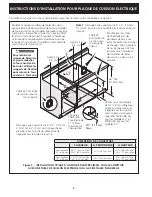
Cooktop Cutout Dimensions
Figure 1 ‑ 30" Model shown only
All dimensions are in inches (cm).
** Allow 2" (5 cm) space below cooktop to clear the electric cable and allow for
installation of the junction box on the wall at the back of the cooktop.
P/N 318205408 (0911) Rev. B
Printed in United States
4" X 8" (10.2 cm x 20.3 cm)
opening at the right rear
to route armored cable
if a panel is present
INSTALLATION AND SERVICE MUST BE PERFORMED BY A
QUALIFIED INSTALLER.
IMPORTANT: SAVE FOR LOCAL ELECTRICAL INSPECTOR'S USE.
READ AND SAVE THESE INSTRUCTIONS FOR FUTURE REFERENCE.
FOR YOUR SAFETY: Do not store or use gasoline or other
flammable vapors and liquids in the vicinity of this or any other appliance.
WARNING
Canada
U.S.A.
* 30" (76.2 cm) min. for unprotected cabinet
24" (61 cm) min. for protected surface
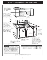
PRODUCT DIMENSIONS
MODEL
A.
WIDTH
B.
DePth
C.
HEIGHT
D.
BOX WIDth
E.
BOX DePth
30’’ Ceramic Model
30 ¾ (78.1)
21 ½ (54.6)
5 (12.7)
29 (73.7)
19 ½ (49.5)
36’’ Ceramic Model
36 ½ (92.7)
21 ½ (54.6)
5 (12.7)
34
5
/
8
(87.9)
19½ (49.5)
CUT OUT DIMENSIONS
F.
WIDTH
G.
DePth
H.
heIght BeLOW
MODEL
MINIMUM
MAXIMUM
MINIMUM
MAXIMUM
COOKtOP
30’’ Ceramic Model
29 ¾ (75.6)
30
1
/
8
(76.5)
20
3
/
8
(51.7)
20 ¾ (52.7)
6 (15.2)
36’’ Ceramic Model
35 ½ (90.2)
35
7
/
8
(91.1)
20
3
/
8
(51.7)
20 ¾ (52.7)
6 (15.2)


