background image

2

ELECTRIC COOKTOP INSTALLATION INSTRUCTIONS

H

G

F

L

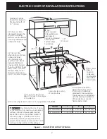
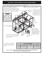
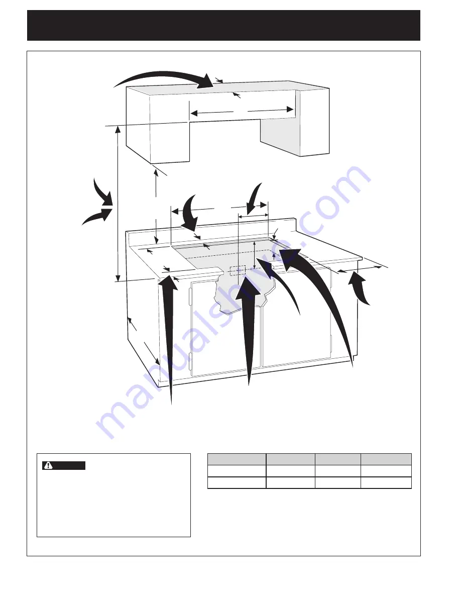
Figure 2 – COUNTERTOP CUTOUT OPENING
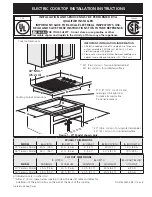
CAUTION

 to eliminate the risk of burns 

or fire resulting from reaching over heated 
surfaces, cabinet storage space located 
above the cooktop should be avoided. If 
cabinet storage is provided, risk can be 
reduced by installing a range hood that 
projects horizontally a minimum of 5" (12.7 
cm) beyond the bottom of the cabinets.

Letters on this figure refer to chart on front page except for 

J, K & L

.

Overhead Cabinet 

Should Not exceed a 

Maximum Depth of 

13" (33 cm)

30" (76.2 cm) Min. 

Clearance Between the 

top of the Cooking 

Platform and the Bottom 

of an Unprotected Wood

or Metal Cabinet

24" (61 cm) Min. 

when Bottom of Wood 

or Metal Cabinet 

is Protected by Not 

Less than 1/8" Flame 

Retardant Millboard 

Covered With Not Less 

than No. 28 MgS Sheet 

Steel, 0.015" (0.4 mm) 

Stainless Steel, 0.024" 

(0.6 mm) Aluminum or 

0.020" (0.5 mm) Copper

2 1/2" (6.4 cm) Min. From 

edge of Cutout to Front edge 

of Countertop

Approximate Location 

of Junction Box

18"

(45.7 cm)

For a drawer installation 

below the cooktop, allow 

8"(20.4cm) of clearance 

underneath the countertop. 

the drawer must not interfere 

with the electrical installation 

of the cooktop or contain 

flammable materials.

Min. From 

edge of 

Cooktop 

to Nearest 

Combustible 

Wall (either 

Side of Unit).

12"

(30.5 cm)

10"

( 25.4 cm)

Min.

K


Min. 

Recommended 

Distance Between 

Rear edge of 

Cutout  and Nearest 

Combustible 

Surface Above 

Countertop

24"

(61 cm)

MODEL

J

K

L

30’’ Ceramic glass

7 ½’’ (19.1 cm)

2’’ (5.1 cm)

30" (76.2 cm)

36’’ Ceramic glass

7 ½’’ (19.1 cm)

2’’ (5.1 cm)

36" (91.4 cm)

Summary of Contents for 318205408(0901)

Page 1: ...States 4 X 8 10 2 cm x 20 3 cm opening at the right rear to route armored cable if a panel is present INSTALLATION AND SERVICE MUST BE PERFORMED BY A QUALIFIED INSTALLER IMPORTANT SAVE FOR LOCAL ELECTRICAL INSPECTOR S USE READ AND SAVE THESE INSTRUCTIONS FOR FUTURE REFERENCE FOR YOUR SAFETY Do not store or use gasoline or other flammable vapors and liquids in the vicinity of this or any other appl...

Page 2: ... cm Min when Bottom of Wood or Metal Cabinet is Protected by Not Less Than 1 8 Flame Retardant Millboard Covered With Not Less Than No 28 MGS Sheet Steel 0 015 0 4 mm Stainless Steel 0 024 0 6 mm Aluminum or 0 020 0 5 mm Copper 2 1 2 6 4 cm Min From Edge of Cutout to Front Edge of Countertop Approximate Location of Junction Box 18 45 7 cm For a drawer installation below the cooktop allow 8 20 4cm ...

Page 3: ...ate circuit fused on both sides of the line a 40A time delay fuse or circuit breaker is recommended DO NOT fuse neutral NOTE Wire sizes and connections must conform with the fuse size and rating of the appliance in accordance with the National Electrical Code ANSI NFPA No 70 latest edition or with CSA standard C22 1 Canadian Electrical Code Part 1 and local local codes and ordinances WARNING An ex...

Page 4: ...th the National Electrical Code ANSI NFPA No 70 latest edition or with CSA Standard C22 1 Canadian Electrical Code Part 1 and local codes and ordinances Risk of electrical shock Failure to heed this warning may result in electrocution or other serious injury This appliance is equipped with copper lead wire If connection is made to aluminum house wiring use only connectors that are approved for joi...

Page 5: ...FPA No 70 latest edition or with CSA Standard C22 1 Canadian Electrical Code Part 1 see Figure 7 Cooktop Nylon spacer Countertop Retainer bracket Figure 7 Checking Operation Refer to the Use and Care Guide for operation CAUTION Do not touch cooktop glass or elements They may be hot enough to burn you Model and Serial Number Location The serial plate is located under the cooktop When ordering parts...

Page 6: ... in oven Figure 9 TYPICAL UNDER COUNTER INSTALLATION OF A SINGLE ELECTRIC BUILT IN OVEN WITH AN ELECTRIC COOKTOP MOUNTED ABOVE Approx 3 7 5 cm Cabinet side filler panels are necessary to isolate the unit from adjoining cabinets Cabinet side filler height should allow for installation of ap proved cooktop models To reduce the risk of personal injury and tipping of the wall oven the wall oven must b...

Page 7: ... 10 2 cm x 20 3 cm pour laisser passer le câble armé s il y a un panneau UN INSTALLATEUR QUALIFIÉ DOIT EFFECTUER L INSTALLATION ET LE SERVICE IMPORTANT CONSERVEZ CES INSTRUCTIONS POUR LES INSPECTEURS LOCAUX LISEZ CES INSTRUCTIONS ET CONSERVEZ LES POUR RÉFÉRENCES ULTÉRIEURES POUR VOTRE SÉCURITÉ N entreposez et n utilisez pas d essence ou d autres produits inflammables à proximité de cet appareil ou...

Page 8: ...ant du dessus de comptoir Dégagement minimum de 30 76 2 cm entre le haut de la surface de cuisson et la base de l armoire en bois ou en métal non protégée L armoire supérieure ne doit pas excéder une profondeur maximale de 13 33 cm Emplacement approximatif de la boîte de jonction Minimum de J du rebord de la plaque de cuisson au mur en matériel inflammable le plus proche de chaque côté de l appare...

Page 9: ... pas de fusible au neutre NOTE Le calibre des fils et leurs connexions doivent être conformes à la capacité des fusibles et à la capacité nominale de l appareil selon le National Electrical Code ANSI NFPA No 70 dernière édition ou avec la norme ACNOR C22 1 Partie 1 du Code canadien d électricité et les codes et les règlements locaux N utilisez pas de rallonge électrique avec cet appareil Son utili...

Page 10: ...les fils blanc et vert des autres et utilisez le fil de mise à la terre pour mettre à la terre l appareil conformément aux codes locaux branchez le conducteur neutre de manière habituelle au circuit neutre voir la figure 5 Si l appareil doit être branché à un câble à 3 fils aux États Unis seulement où les codes locaux permettent la connexion du fil de mise à la terre du châssis au neutre blanc Voi...

Page 11: ...ace fourni à cet effet La plaque de cuisson doit être centrée pour empêcher l accumulation de cha leur pouvant entraîner des dommages par la chaleur ou le feu voir Figure 8 Figure 6 Figure 8 L C 6 entretoises en nylon 2 supports de fixation Positionnez les supports de fixation sur la ligne centrale de l ouverture du comptoir Vérification de fonctionnement Référez vous au Guide de l utilisateur pou...

Page 12: ...ontre plaqué de 1 9 cm d épaisseur monté sur deux solives et à égalité avec le coup de pied La base doit pouvoir supporter 150lbs 68 kg pour les modèles 27 et 200lbs 90 kg pour les modèles 30 Découpez une ouverture de 4 X 4 10 2cm X 10 2cm à 2 5 cm du côté gauche du plancher pour la sortie du câble armé de l appareil vers la boîte de jonction Il faut fermer les côtés de l habitacle par des panneau...

Reviews: