background image

2

CONTENTS

Pre-Installation Requirements..........................................................................................................................................2
Electrical Requirements..................................................................................................................................................3
Gas Supply Requirements........................................................................................................................................................3
Exhaust System Requirements......................................................................................................................................3-5
Location of Your Dryer....................................................................................................................................................5
Rough-In Dimensions.....................................................................................................................................................6
Reversing Door Swing.................................................................................................................................................7
Unpacking ...................................................................................................................................................................8
General Installation.......................................................................................................................................................8
Replacement Parts........................................................................................................................................................8
Mobile Home Installation...............................................................................................................................................9
Electrical Installation.....................................................................................................................................................9
Grounding Requirements..............................................................................................................................................10
Gas Connection..........................................................................................................................................................10
Electrical Connections—3-wire........................................................................................................................................11
Electrical Connections—4-wire........................................................................................................................................11
Français....................................................................................................................................................................12-21
Español..................................................................................................................................22-31

SAFETY INSTRUCTIONS

Before beginning installation, carefully read these instructions. This will simplify the installation and ensure the dryer
is installed correctly and safely. Leave these instructions near the Dryer after installation for future reference.

NOTE: 

The electrical service to the Dryer must conform with local codes and ordinances and the latest edition of the National

Electrical Code, ANSI/NFPA 70, or in Canada, the Canadian electrical code C22.1 part 1.

NOTE: 

The gas service to the Dryer must conform with local codes and ordinances and the latest edition of the National Fuel Gas

Code ANSI Z223.1, or in Canada, CAN/ACG  B149.1-2000

NOTE: 

The Dryer is designed under ANSI Z 21.5.1  or ANSI/UL 2158 - CAN/CSA C22.2 No. 112 (latest editions) for 

HOME USE

only

. This Dryer is not recommended for commercial applications such as restaurants or beauty salons, etc.

  For your safety the information in this manual must be followed to minimize the risk of fire or explosion or to

prevent property damage, personal injury or loss of life.
- Do not store or use gasoline or other flammable vapors and liquid in the vicinity of this or any other appliance.

- WHAT TO DO IF YOU SMELL GAS

·

Do not try to light any appliance.

·

Do not touch any electrical switch; do not use any phone in your building.

·

Clear the room, building or area of all occupants.

·

Immediately call your gas supplier from a neighbor’s phone. Follow the gas supplier's instructions.

·

If you cannot reach your gas supplier, call the fire department.

Installation and service must be performed by a qualified installer, service agency or the gas supplier.

PRE-INSTALLATION REQUIREMENTS

Tools and Materials Required for Installation:

 1.  Phillips head screwdriver.
 2.  Channel-lock adjustable pliers.
 3.  Carpenter's level.
 4.  Flat or straight blade screwdriver.
 5.  Duct tape.
 6.  Rigid or flexible metal 4 inch (10.2 cm) duct.
 7.  Vent hood.
 8.  Pipe thread sealer (Gas).
 9.  Plastic knife.

Your safety and the safety of others is very important.

We have provided many important safety messages in the Use & Care Guide, Operating Instructions, Installation Instructions and
on your appliance. Always read and obey all safety messages.


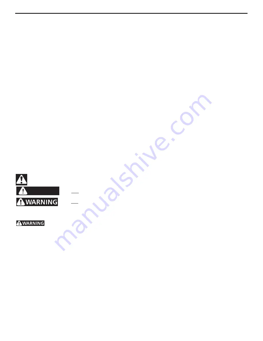
            This is the safety alert symbol. This symbol alerts you to hazards that can kill  or hurt you or others.   All safety messages

             will be preceded by the safety alert symbol and the word 

"DANGER"

 or 

"WARNING"

. These words mean:

DANGER

All safety messages will identify the hazard, tell you how to reduce the chance of injury, and tell you what can happen if the
instructions are not followed.

You will be killed or seriously injured if you don't follow instructions.

You can be killed or seriously injured if you don't follow instructions.

Summary of Contents for AGQ6700FE - 27" Gas Dryer

Page 1: ...1 Installation Instructions Gas Electric Dryer Instructionsd Installation Sécheuse à Gaz ou Électrique Instruccionesparalainstalación Secadora a Gas y Eléctrica www frigidaire com P N 137101000 0806 ...

Page 2: ... injury or loss of life Do not store or use gasoline or other flammable vapors and liquid in the vicinity of this or any other appliance WHAT TO DO IF YOU SMELL GAS Do not try to light any appliance Do not touch any electrical switch do not use any phone in your building Clear the room building or area of all occupants Immediately call your gas supplier from a neighbor s phone Follow the gas suppl...

Page 3: ...connecting pipe that is not plastic coated Stainless steel or plastic coated brass MUST be used 1 Installation MUST conform with local codes or in the absence of local codes with the National Fuel Gas Code ANSI Z223 1 latest edition 2 The gas supply line should be of 1 2 inch 1 27 cm pipe 3 If codes allow flexible metal tubing may be used to connect your dryer to the gas supply line The tubing MUS...

Page 4: ... of lint in the exhaust system Plug ging the system could create a fire hazard as well as increase drying times Do not screen the exhaust ends of the vent system nor use any screws rivets or other fastening means that extend into the duct and catch lint to assemble the exhaust system Lint can become caught in the screen on the screws or rivets clogging the duct work and creating a fire haz ard as ...

Page 5: ... TOP FRONT Alcove 0 0 cm 0 0 cm Closet 0 0 cm 0 0 cm 1 2 54 cm Closet door ventilation required 2 louvered openings each 60 square inches 387 square centimeters 3 inches 7 6 cm from bottom and top of door This dryer MUST be exhausted outdoors 5 The following illustrations show minimum clearance dimensions for proper operation in a recess or closet installation Venting vertical through a roof may e...

Page 6: ...3 123 123 123 123 123 123 123 123 123 123 27 68 58 5 13 97 29 75 57 13 34 29 5 12 70 2 6 03 3 8 34 86 36 35 88 90 2 25 5 72 Stacked Dryer Installation Dimensions To front of cabinet 28 25 71 76 To clear kobs 28 75 73 03 To clear door 29 5 74 93 To clear open door 53 134 62 13 5 34 29 27 68 58 Electrical supply on rear of unit 2 375 6 03 Gas supply pipe on rear of unit 72 00 172 88 38 25 97 16 41 0...

Page 7: ... bottom screw first Round plug Round plug Rectangular plug 6 7 7 Remove the two hinge attachment screws one square plug two round plugs and one metal strike from the inner door 8 Rotate the hinge and reattach it to the opposite side of the inner door 9 Dispose of the old metal strike and install the new strike included in the literature pack in the opposite side of the inner door Reinstall the rou...

Page 8: ...ase review the Avoid Service Checklist located in your Use and Care Guide be fore calling for service 7 Place these instructions in a location near the dryer for fu ture reference 8 To stack your dryer on a compatible washer visit web site www frigidaire com call your local dealer or call the Toll Free number 1 800 444 4944 to find your local distribu tor to purchase stacking kit accessory part nu...

Page 9: ... Dryer The following are specific requirements for proper and safe electrical installation of your dryer Failure to follow these instructions can create electrical shock and or a fire hazard This appliance MUST be properly grounded Electrical shock can result if the dryer is not prop erly grounded Follow the instructions in this manual for proper grounding Do not use an extension cord with this dr...

Page 10: ...ord connected dryer 1 The dryer must be grounded In the event of a malfunc tion or breakdown grounding will reduce the risk of elec trical shock by a path of least resistance for electrical cur rent 2 Since your dryer is equipped with a power supply cord having an equipment grounding conductor and a ground ing plug the plug must be plugged into an appropriate outlet that is properly installed and ...

Page 11: ...curely so that the strain relief does not turn 9 Reinstall the terminal block cover ELECTRICAL CONNECTIONS FOR 4 WIRE SYSTEM USA ELECTRIC Dryer 1 Remove the screws securing the terminal block access cover and the strain relief mounting bracket located on the back of the dryer upper corner 2 Install a U L approved strain relief in the entry hole of the mounting bracket Finger tighten the nut only a...

Page 12: ...peler le service de protection des incendies L installation et les réparations doivent être effectuées par un service de réparation un technicien qualifié ou le fournisseur de gaz Table des matières Avant l installation 12 Installation électrique 13 Alimentation en gaz 13 Évacuation de l air 13 15 Emplacement de la sécheuse 15 Dimensions de l emplacement 16 Porte réversible 17 Déballage 18 Install...

Page 13: ...re remplir la norme UL 215Å Les matériaux de ventilation flexibles peuvent s abimer facilement et recueillir du duvet Cesconditionsobstruerontlacirculationd airdelaSécheuse de vêtements et augmenteront le risque d incendie S assurer qu il n y a pas de charpie dans la conduite existante avant d installer la conduite de la sécheuse Risqued incendie uneSécheusedevêtementdoitêtre aéré à l air libre N ...

Page 14: ... 53 m 28 po 4 87 m 16 po 10 2 10 2 10 2 10 2 10 2 cm cm cm cm cm 4 po 4 po 4 po 4 po 4 po 10 2 10 2 10 2 10 2 10 2 cm cm cm cm cm 4 po 4 po 4 po 4 po 4 po 6 35 6 35 6 35 6 35 6 35 cm cm cm cm cm 2 1 2 po 2 1 2 po 2 1 2 po 2 1 2 po 2 1 2 po 6 35 6 35 6 35 6 35 6 35 cm cm cm cm cm 2 1 2 po 2 1 2 po 2 1 2 po 2 1 2 po 2 1 2 po 0 9 14 m 30 po 5 49 m 18 po 1 6 71 m 22 po 4 27 m 14 po 2 4 27 m 14 po 3 05...

Page 15: ...ERIEUR 5 Lesillustrationsquisuiventdonnentledégagementminimumpouruneinstallationdans une alcôve ou un placard PORTE DU PLACARD PORTE DU PLACARD PORTE DU PLACARD PORTE DU PLACARD PORTE DU PLACARD 387 1 cm 60 po 387 1 cm 60 po 0 cm 0 po 0 cm 0 po 0 cm 0 po 0 cm 0 po 0 cm 0 po 2 54 cm 2 54 cm 2 54 cm 2 54 cm 2 54 cm 1 po 1 po 1 po 1 po 1 po 0 cm 0 po 0 cm 0 po 0 cm 0 po 0 cm 0 po 0 cm 0 po Ilfautinsp...

Page 16: ... 76 Aux boutons clairs 28 75 73 03 À la poignée claire de porte 29 5 74 93 À l espace libre ouvrez la porte 53 134 62 13 5 34 29 27 68 58 Alimentation électrique sur l arrière de l unité 2 375 6 03 Pipe d offre de gaz sur l arrière de l unité 72 00 172 88 38 25 97 16 41 00 97 16 Ligne taille centrale pour arrière droit parti passage 4 375 11 12 Echappements Latéraux 15 8 4 13 25 8 6 67 5 0 12 7 Li...

Page 17: ...e bouchon carré les deux bouchons ronds et la gâche en métal de la contre porte 8 Faites une rotation de la charnière et fixez la du côté opposé de la contre porte 9 Jetez la vielle gâche en métal et posez la nouvelle gâche comprise dans la trousse de documentation sur le côté opposé de la contre porte Reposez les bouchons ronds et le bouchon carré dans les trous laissés par la charnière et les vi...

Page 18: ... enfants risqueraient de s en servircommejouet Lescartonsrecouvertsd untapis d uncouvre lit ou d une feuille de plastique peuvent former une chambre étanche et faire suffoquer un enfant Placer le matériel d emballage dans une poubelle ou les mettre hors de portée des enfants Les directives qui figurent dans cette notice et dans les autres documents qui accompagnent la sécheuse ne sauraientcouvrirt...

Page 19: ...cuivre REMARQUE Les sécheuses qui fonctionnent avec une alimentation de 208 volts auront un temps de séchage plus long que celles qui utilisent une alimentation de 240 volts INSTALLATION DANS UNE MAISON MOBILE 1 L évacuation d air de la sécheuse DOIT se faire à l extérieur de la maison à l éxterieur et non pas au dessous de la maison mobile à l aide de conduit en métal non inflammable à l épreuved...

Page 20: ...ementoudepanne lamiseàlaterreréduitlesrisques choc électrique en offrant un parcours de moindre résistance aucourant 2 Puisque la sécheuse est pourvue d un cordon d alimentation électrique comportant un conducteur et une fiche de terre la fiche doit être branchée dans une prise murale à conducteur en cuivre convenablement raccordée au réseau et mise à la terre conformément à tous les codes et ordo...

Page 21: ...du panneau de branchement ainsi que le support de montage du détendeur situés dans le coin supérieur à l arrière de la sécheuse 2 Poser un détendeur approuvé par U L dans le trou du support oùs insèrelecordond alimentation Serrersimplementl écrou à la main pour le moment 3 Enfileruncordond alimentationNEMA10 30approuvéparU L de 30 A de type SRDT dans le détendeur 4 Fixer le conducteur neutre condu...

Page 22: ...s personales o la muerte GUARDE ESTAS INSTRUCCIONES Noalmaceneniutilicegasolinauotrosvaporesylíquidosinflamablesenlaproximidaddeésteodecualquierotroartefactoeléctrico QUEDEBEHACERSIPERCIBEOLORAGAS No trate de encender ningún artefacto eléctrico Notoqueningúninterruptoreléctrico nouseningúnteléfonoensuedificio Haga salir a todos los ocupantes de la habitación del edificio y del lugar Llame a su pro...

Page 23: ... cualquier otra obstrucción Los siguientes requerimientos son específicos para el funcionamiento correcto y seguro de su secadora El incumplimiento de estas instrucciones puede causarprolongaciónexcesivadeltiempodesecadoyriesgos de incendio No instale la Secadora con materiales de ventilación plásticos flexibles EnCanadáylosEstadosUnidossielconductoesdemetal tipohojadealuminio éstedebeserdeuntipoe...

Page 24: ...ebeserventiladaalexterior delavivienda Noventilelasecadoraaunachimenea pared techo ático pasajes entre pisos o cualquier espacio oculto de la vivienda Lassecadorasderopaproducenpelusacombustible Sinoseventila la secadora al exterior algunas pelusas finas se acumularán en el área de lavandería La acumulación de pelusa en cualquier área de la vivienda puede constituir un peligro sanitario y un riesg...

Page 25: ...mente La capacidad de desahogo del un sistema disminuirá si es comprimido El sistema de desahogo debe de ser inspeccionado y limpiado por lo menos cada 18 meses de uso normal Cuanto más la secadora está utilizada más debe verificar el buen funcionamiento del sistema de desahogo y de la tapa del orificio de ventilación UBICACIÓN DEL ESCAPE Todaslassecadorasvienendefábricaequipadasconescapetrasero S...

Page 26: ... 123 123 123 123 123 123 123 123 123 123 123 123 123 123 123 123 123 123 123 123 123 123 123 123 123 123 123 123 123 123 123 123 123 123 123 123 123 123 123 123 123 123 123 123 123 123 123 123 123 123 123 123 123 123 123 123 123 123 123 123 123 123 123 123 123 Al frente del gabinete 28 25 71 76 A las perillas claras 28 75 73 03 A las perillas puerta 29 5 74 93 En ei claro abra la puerta 53 134 62 ...

Page 27: ...tapón cuadrado dos tapones redondos y un percutor de metal 8 Gire la bisagra y vuelva a engancharla a la parte opuesta de la contrapuerta 9 Deseche el viejo percutor de metal e instale uno nuevo incluido en el paquete de documentación en el lado opuesto de la contrapuerta Vuelva a instalar los tapones redondos y el tapón cuadrado en los agujeros que dejaron la bisagra y los tornillos de la bisagra...

Page 28: ...ciones incluidas en este manual y en el resto de la documentación que se entrega con la secadora nopuedencubrirtodaslassituacionesocondicionesposiblesque puedan presentarse Por lo tanto se DEBEN seguir prácticas segurasytenercuidadocuandoseinstala poneenfuncionamiento y mantiene cualquier artefacto doméstico DESEMBALAJE 1 Utilizando las cuatro esquineras de embarque de la caja de cartón dosacadala...

Page 29: ...ssecadorasqueoperanconunsuministrodeenergíade 208voltiosusaránmástiempodesecadoqueaquellasqueoperan con un suministro de energía de 240 voltios INSTALACIÓN EN CASAS MÓVILES 1 El tubo de escape de la secadora DEBE ser instalado hacia el exterior Elescapedebecolocarseenlaparteexteriorynodebajo de la casa móvil Debe usarse ducto de metal que no sea combustible Elductodemetaldebetenercuatropulgadas 10...

Page 30: ... la puesta a tierra reducirá el riesgo de choque eléctrico proporcionando un trayecto de menor resistencia a la corriente eléctrica 2 Sisusecadoraestáequipadaconuncordóneléctricoqueposee unconductordepuestaatierradelequipoyunenchufedepuesta atierra dichoenchufe DEBEserconectadoauntomacorriente adecuado debidamente instalado y puesto a tierra de acuerdo contodosloscódigosyreglamentoslocales Sitiene...

Page 31: ...terminales CABLEDE PUESTAA TIERRA NEUTRAL ROJO NEGRO BLANCO TUERCA SOPORTE DEMONTAJE DEL ANCLAJE DECABLE ATORNILLE LA TUERCA EN ESTAS ROSCAS CONDUCTOR VERDE DE CORDÓN ELÉCTRICO TORNILLO VERDE DE PUESTA A TIERRA BORNE PLATEADO TABLERODE TEMINALES CORDÓN ELÉCTRICO TOMACORRIENTE TETRAFILAR TIPICO CORDÓN ELÉCTRICO TETRAFILAR TIPICO 240 V NEGRO NEUTRO BLANCO 240 V ROJO PUESTA A TIERRA VERDE CONEXIÓNES ...

Reviews: