background image

Summary of Contents for BKQE7071MT0

Page 1: ...TABLE OF Important Safety Instructions 2 3 Installation Requirements 4_10 Installed Dryer Dimensions 1 Installation Instructions 12 17 CONTENTS _versing Door 18 2 1 Y iii ii Fran_ais 23 E J P_ _J o o 3 ...

Page 2: ...uty salons etc Do not install a clothes dryer with flexible plastic venting material Flexible venting materials are known to collapse be easily crushed and trap lint These conditions will obstruct clothes dryer airflow and increase the risk of fire Do not stack a dryer on top of washer already installed on pedestal Do not stack dryer on top of another dryer Do not stack washer on top of dryer Do n...

Page 3: ...ting Free flowing clear of lint buildup 4 inch 102 mm rigid or semi rigid ducting of minimal length and turns NO foil or plastic venting material Approved vent hood exhausted to outdoors Leveling Dryer is level side to side and front to back Cabinet is setting solid on all corners Gas Supply Gas Dryer Manual shutoff valve present in supply All connections sealed with approved sealer and wrench tig...

Page 4: ...cessible when the dryer is in the installed position GROUNDING CONNECTION See Grounding requirements in Electrical Installation section 3 WIRE POWER SUPPLYCORD KIT not supplied 3 wire receptacle NEMA type 10 30R The dryer MUST employ a 3 conductor power supply cord NENA 10 30 type SRDT rated at 240 volt AC minimum 30 amp with 3 open end spade lug connectors with upturned ends or closed loop connec...

Page 5: ...ine should be 1 2 inch 1 27 cm pipe 3 If codes allow flexible metal tubing may be used to connect your dryer to the gas supply line The tubing MUST be constructed of stainless steel or plastic coated brass 4 The gas supply line MUST have an individual shutoff valve 5 A 1 8 inch 0 32 cm N RT plugged tapping accessible for test gauge connection MUST be installed immediately upstream of the gas suppl...

Page 6: ...ure to follow these instructions can create excessive drying times and fire hazards The following are specific requirements for proper and safe operation of your dryer FIRE HAZARD Do not install a clothes dryer with flexible plastic or metal foil venting materials Flexible venting materials are known to collapse be easily crushed and trap lint These conditions will obstruct clothes dryer airflow a...

Page 7: ...g in a fire hazard Do not screen the exhaust ends of the vent system or use any screws rivets or other fasteners that extend into the duct to assemble the exhaust system Lint can become caught in the screen on the screws or rivets clogging the duct work and ii creating a fire hazard as well as increasing drying ii times Use an approved vent hood to terminate the duct outdoors and seal all joints w...

Page 8: ...xpose the exhaust system to down drafts causing an increase in vent restriction Running the exhaust system through an uninsulated area may cause condensation and faster accumulation of lint Compression or crimping of the exhaust system will cause an increase in vent restriction The exhaust system should be inspected and cleaned a minimum of every 18 months with normal usage The more the dryer is u...

Page 9: ...e for other important exhaust venting system requirements 5 When installing a gas dryer into a mobile home a provision must be made for outside make up air This provision is to be not less than twice the area of the dryer exhaust outlet 6 Installer MUST anchor this 1 dryer or 2 dryer mounted on pedestal to the floor with approved Mobile Home Installation Kit P N 137067200 Clearance requirements EX...

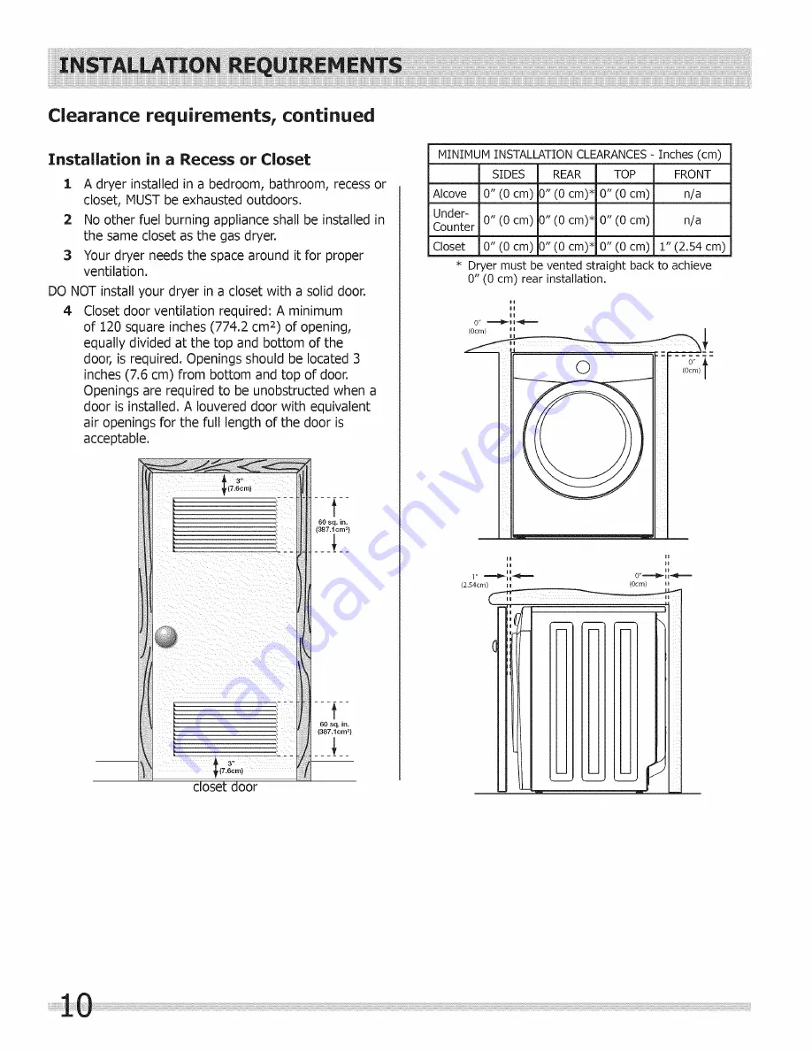
Page 10: ...s 774 2 cm 2 of opening equally divided at the top and bottom of the door is required Openings should be located 3 inches 7 6 cm from bottom and top of door Openings are required to be unobstructed when a door is installed A Iouvered door with equivalent air openings for the full length of the door is acceptable 3 7 6c m closet door 1 60 sq in 387 1cm f 60 sq in 387 1cm _ MINIMUM INSTALLATION CLEA...

Page 11: ... height for rear vent 34 5cm to center of rear vent 51 4 131cm to clear open door 30 3 77cm to front of closed door 71 5 182cm water supply connection on rear of unit 1 gas supply pipe on rear of gas unit 37 94cm 27 0 68 5cm 0 0 drain hose on rear of unit 3 electrical supply on rear of unit power cord on rear of unit 2 centerline height for rear vent 39 99cm 19 0 48cm To obtain these minimal depth...

Page 12: ...The proper wiring and receptacle is a copper wired power cord with a copper wired receptacle Dryers operating on 208 volt power supply will have longer drying times than dryers operating on 240 volt Grounding requirements Electric dryer USA ELECTRICAL SHOCK HAZARD Improper connection of the equipment grounding conductor can result in a risk of electrical shock Check with a licensed electrician if ...

Page 13: ...d in accordance with all local codes and ordinances If in doubt call a licensed electrician 3 DO NOT modify the plug provided with this appliance If it will not fit the outlet have a proper outlet installed by a qualified electrician Grounding requirements Gas dryer USA and Canada 1 The dryer is equipped with a three prong grounding plug for your protection against shock hazard and should be plugg...

Page 14: ...LOW Shutoff Flare _ Flare Valve Union Union losea_ _ t t t Nipple Flexible Inlet Pipe on Open Connector Back of Dryer All connections must be wrench tightened The supply line must be equipped with an approved manual shutoff valve This valve should be located in the same room as the dryer and should be in a location that allows ease of opening and closing Do not block access to the gas shutoff valv...

Page 15: ... cord neutral center wire conductor to the SILVER colored center terminal on the terminal block Tighten the screw securely 6 Attach the remaining two power cord outer conductors to the outer BRASScolored terminals on the terminal block Tighten both screws securely _ _ Access cover _jj screw Line 2 __z L_ _ BRASSterminal Line 1 BRASSterminal _ internal ground GREEN screw Terminal screw recovery slo...

Page 16: ...ire to the cabinet with the ground GREEN screw Tighten the screw securely 7 Move the internal dryer harness ground BLACK wire to the terminal block and attach it along with the neutral WHITE power cord wire conductor to the center SILVER colored terminal on the terminal block Tighten the screw securely 8 Attach the RED and BLACK power cord conductors to the outer BRASS colored terminals on the ter...

Page 17: ... and discard door tape Be sure the power is off at a circuit breaker fuse box before plugging the power cord into an outlet 3 Plug the power cord into a grounded outlet 4 Turn on the power at the circuit breaker fuse box 5 Read the Use Care Guide provided with the dryer It contains valuable and helpful information that will save you time and money 6 If you have any questions during initial operati...

Page 18: ...LOT IN FRONT PANEL T POST ON DOOR HINGE 4 5 Gently place dryer door face down on fiat covered work surface Locate the 5 indented head screws no 1 5 in the small circular recesses at 11 1 4 6 and 8 o clock positions of the inner door Remove and save these 5 screws 2 7 5 4 Do not attempt to remove the 2 tamper resistant screws that hold the inner glass n place 6 Locate the 2 pan head screws no 6 7 o...

Page 19: ...3 Turn the inner door assembly back over and locate the 2 pan head hinge screws Remove and save the 2 screws and separate the hinge from inner door assembly HINGE SCREWS 4 IN From the back side of the inner door pinch the retaining tabs of the plastic square plug to release it Save square plug for reinstallation Carefully remove the 2 round plugs from the inner door and move them to the opposite h...

Page 20: ...the supports for the hinge cutout cover Pivot the inner door down onto the outer door 3 Replace indented head screws no 1 5 removed earlier Take care not to strip out the plastic holes 4 Replace pan head screws no 6 7 removed earlier Take care not to strip out the plastic holes 2 5 Locate new metal strike supplied with dryer manuals Grip new strike with pliers as shown below Firmly insert the stri...

Page 21: ... the mounting holes T POST ON DOOR HINGE T SLOT IN FRONT PANEL 2 While supporting the door install the upper pan head screw first and then the lower one Close the door and test operation of hinge strike and latch Correctly installed hinge screws will press hinge flush to front panel Any gap between hinge and front panel will cause misalignment of strike to latch ...

Page 22: ... ofa MOBILE HOME INSTALLATION KIT DRYING RACK P N 137067300 Depending on the model you purchased a drying rack may have been included in the initial purchase of your dryer If your model did not include a drying rack or you desire another drying rack you may order one UNIVERSAL APPLIANCE WRENCH P N137019200 A UNIVERSAL APPLIANCE WRENCH isavailable toaidindryer washer pedestal feetadjustment TOUCH U...

Page 23: ...TABLE DES MATIERES Dimensions appareil install6 33 Accessoires 44 ...

Page 24: ...nts des salons de coiffure etc N installez pas une s_cheuse avec du materiel d _vacuation en plastique ou en feuille m_tallique flexible Le mate riel de ventilation flexible peut s _craser facilement et emprisonner la charpie Ces conditions nuiraient _ I _coule ment d air de votre s_cheuse et pourraient accroTtre le risque d incendie Ne superposez pas une s_cheuse sur une laveuse d_j_ install_e su...

Page 25: ...a AUCUN materiel de ventilation en papier d aluminium ou en plastique 1 1Le syst_me d _chappement dolt _vacuer I air a I ext_rieur a I aide d un _vent approuve Mise _ niveau 1 1La s_cheuse est au niveau lat_ralement et de I avant vers I arri_re Les quatre coins de la caisse reposent fermement sur le plancher Alimentation au gaz s_cheuse au gaz l l Le conduit d alimentation comporte un robinet d ar...

Page 26: ..._cheuse est _ sa position de fonctionnement CONNEXION DE MISE _ LA TERRE Consultez la rubrique Exigences de mise _ la terre dans la section d installation _lectrique TROUSSE DE CORDON D ALIMENTATION A TROIS FILS non fournie Prise _ 3 alv oles NEMA type 10 30R La s_cheuse DOIT utiliser un cordon d alimentation trois ills NEMA 10 30 de type SRDT d une capacit_ de 240 volts c a et d au moins 30 amper...

Page 27: ...s Iocaux ou au code national sur le combustible ANSI Z223 1 derni_re version s il n existe pas de codes Iocaux 2 Le tuyau d alimentation en gaz dolt _tre d un diam_tre int6rieur de 1 27 cm 1 2 po 3 Si les codes le permettent un tuyau m6tallique flexible peut 6tre utilis6 pour raccorder votre s6cheuse au tuyau d alimentation en gaz Le tuyau DOIT 6tre fabriqu_ en acier inoxydable ou en laiton avec r...

Page 28: ... pourrait augmenter d_mesur_ment les temps de s_chage et entra ner des Vous trouverez ci dessous les exigences pour I utilisation ad6quate et s6curitaire de votre appareil RISQUE D INCENDIE N installez pas une s_cheuse avec du materiel d _vacuation en plastique ou en feuille m_tallique flexible Le materiel de ventilation flexible peut s _craser facilement et emprisonner la charpie Ces conditions n...

Page 29: ...i_re _ ce qu ils se prolongent dans la ii conduite du syst_me d _vacuation De la charpie pourrait s accumuler sur le grillage les vis ou les rivets et obstruer I _coulement d air dans le syst_me entraTnant un risque d incendie et ii I augmentation des temps de s_chage Utilisez une bouche d _vacuation approuv_e pour terminer la conduite _ I ext_rieur et scellez tousles joints avec du ruban m_talliq...

Page 30: ... condensation et I accumulation plus rapide de charpie Le fair de comprimer ou de pincer le syst_me d _vacuation entraTnera I augmentation de la restriction dans le syst_me Le syst_me d _vacuation dolt 6tre inspect_ et v_rifi_ au moins tousles 18 mois avec un usage normal Plus I appareil est utilis_ plus la p_riode de v_rification du syst_me et de la bouche d _vacuation dolt _tre raccourcie Direct...

Page 31: ... 5 Lors de I installation d une s4cheuse _ gaz dans une maison mobile des dispositions doivent 6tre prises pour permettre I entr4e d air d appoint de I ext4rieur Cette installation ne doit pas mesurer moins de deux fois la surface de la bouche d 6vacuation 6 L installateur DOIT ancrer 1 cette s4cheuse ou 2 la monter sur un socle au sol avec une trousse d installation de maison mobile n de piece 13...

Page 32: ...rture d au moins 774 2 cm2 120 po2 divis6e 6galement au dessus et au dessous de la porte est requise Les ouvertures doivent 6tre situ_es _ 7 6 cm 3 po du haut et du bas de la porte Les ouvertures ne doivent pas 6tre obstru6es Iorsqu une porte est install6e Une porte persiennes dont les ouvertures sur I ensemble de la porte sont 6quivalentes aux recommandations peut 6tre utilis6e 3 7 6cm Porte de p...

Page 33: ...I _vent arri_re 51 4 131cm Avec la porte grande ouverte 30 3 77cm partir de I avant de la porte Iorsqu elle est ferm6e F J m 71 5 182cm Raccord de I alimentation en eau _ t arri re de la laveuse _ Alimentation en gaz _ l arri re de Fappareil _ gaz 37 94cm 27 0 68 5cm O O Tuyau de vidal I arri re de la laveuse 3 Alimentation _lectrique I arri_re de la s6cheuse Hauteur de la ligne centraie de I _ven...

Page 34: ... qui pourrait entra_ner un court circuit II faut utiliser un cordon une fiche et une prise avec des ills en cuivre Les s6cheuses aliment6es par une tension de 208 V poss6deront des temps de s6chage plus longs qu une s6cheuse aliment6e par une tension de 240 V Exigences de rnise ia terre S6cheuse 61ectrique E U RISQUE DE CHOC ELECTRIQUE Un raccordementinad_quat du conducteur de mise _ la terrede i ...

Page 35: ...el un _lectricien qualifi 3 NE HODIFIEZ PAS la fiche fournie avec cet appareil Si elle ne s ins_re pas dans la prise demandez _ un _lectricien qualifi_ d installer la prise adapt_e Exigences de raise ia terre S_cheuse gaz E U et Canada 1 Cet appareil est muni d une fiche _ trois broches mise _ la terre pour assurer votre protection contre les chocs _lectriques Cette fiche dolt _tre branch_e direct...

Page 36: ...ord d arr_t union _ union manuel _vasement _vasement _ _ Duse Raccord Tuyau d entr_e Ouvert flexible raccord6 _ I arri6re de la s6cheuse Tousles raccords doivent tre serr_s au moyen d une cl6 La conduite d alimentation doit _tre munie d un robinet d arr_t approuv_ Ce robinet dolt _tre situ_ dans la ii meme piece que la s_cheuse et plac_ de mani_re _ _tre facilement accessible Ne bloquez pas I acc_...

Page 37: ...rrez bien la vis 6 Fixez les deux autres ills aux bornes externes en LAITON du bornier Serrez bien les deux vis __ Vis du panneau __ T _ j _ _ d acc_s F Bloc de __ _J _r anc he me nt Fil 2 __f Borne en LAITON _ Fil neutre _L __ Borne an ARGENT _ _ vI_ Borne en LAITON Mise A la terre interne Vis VERTE Installez un r_ducteur de tension certifi_ UL ici Fente de r_cup_ration pour les vis des bornes RI...

Page 38: ...6placez le fil de mise _ la terre du faisceau 61ectrique interne NOTE au bornier et fixez le avec le fil neutre du cordon d alimentation BLANC _ la borne centrale ARGENT du bornier Serrez bien lavis 8 Fixez les ills ROUGE et NOIR du cordon d alimentation aux bornes externes en LAITON du bornier Serrez bien les deux vis RISQUE DE CHOC ELECTRIQUE N effectuez pas de courbe soudaine et ne pincez pas l...

Page 39: ...e I alimentation _lectrique est couple au disjoncteur ou au boitier de fusibles avant de brancher le cordon d al mentation dans une Prise _lectrique 3 Branchez le cordon d alimentation _ la prise _lectrique mise _ la terre 40uvrez I alimentation _lectrique au disjoncteur ou au bo tier de fusibles 5 Reportez vous au Guide d utilisation et d entretien fourni avec la s_cheuse II contient des renseign...

Page 40: ...A CHARNIERE DE LA PORTE 4 5 Placez soigneusement la porte de la s_cheuse face contre terre sur la surface de travail protegee Rep_rez les 5 vis _ t_te dentel_e nos 1 _ 5 dans les petits enfoncements circulaires situ_s sur la partie interne de la porte Ces petits enfoncements sont situ_s _ 11 h 1 h 4 h 6 h et 8 h _ I int_rieur de la porte Retirez les 5 vis et conservez les 2 7 5 4 Ne tentez pas d e...

Page 41: ...e 3 Retournez la partie interne de la porte pour avoir acc_s aux languettes de retenue de la g_che m6tallique Retirez les languettes au moyen de pinces etez I ancienne g_che m6tallique 4 _ partir de I arri_re de la partie interne de la porte pincez les languettes de retenue du bouchon carr6 en plastique pour le d6gager Conservez le bouchon en vue d une r6installation Enlevez d61icatement les 2 bou...

Page 42: ..._re Ensuite faites pivoter la partie interne de la porte dans la partie externe 3 R_installez les vis _ t_te dentel_e nos 1 _ 5 retirees pr_c_demment Prenez garde de ne pas endommager le filet des trous en plastique 4 R_installez les vis _ t_te cylindrique nos 6 et 7 retirees pr_c_demment Prenez garde de ne pas endommager le filet des trous en plastique 5 2 Rep6rez la nouvelle g_che m6tallique fou...

Page 43: ...GE EN T DE LA CHARN EREDE LA PORTE FENTE EN T DU PANNEAU AVANT 2 j i i Tout en tenant la porte installez d abord la vis t_te cylindrique sup ieure puis la vis inf ieure I Fermez la porte et v6rifiez le fonctionnement de la charni e de la g_che et du Ioquet Si elles sont installees correctement les vis de la charniere seront de niveau avec le panneau avant Tout espacement entre la charniere et le p...

Page 44: ... i TAGI_RE DE SECHAGE PIECEN 137067300 Selon le module que vous avez achet_ il se peut qu une _tag_re de s_chage air _t_ incluse dans I achat initial de votre s_cheuse Si votre module ne comprenait pas d _tag_re de s_chage ou que vous en d_sirez une autre il vous est possible d en commander une CLE D APPAREIL UNIVERSELLE PII_CE N 137019200 UNE CLI D APPAREIL UNIVERSELLE est offerte pour fadiiter i...

Reviews: