Section 3 Troubleshooting and Testing
3-8
Procedure
Letter
J
K
Component Test
HOOD THERMOSTAT TEST
1. Disconnect the power supply cord, and then remove outer case.
2. Open the door and block it open.
3. Discharge high voltage capacitor. (See Warnings and Instructions on page 3-1)
4. A continuity check across the thermal cut-out terminals should indicate an open circuit unless
the temperature of the thermal cut-out reaches approximately 140°F (60°C) or more. At that
temperature, the contacts will close. The thermal cut-out opens automatically at approximately
113°F (45°C).
5. Reconnect all leads removed from components during testing.
6. Reinstall the outer case (cabinet).
7. Reconnect the power supply cord after the outer case is installed.
8. Run the oven and check all functions.
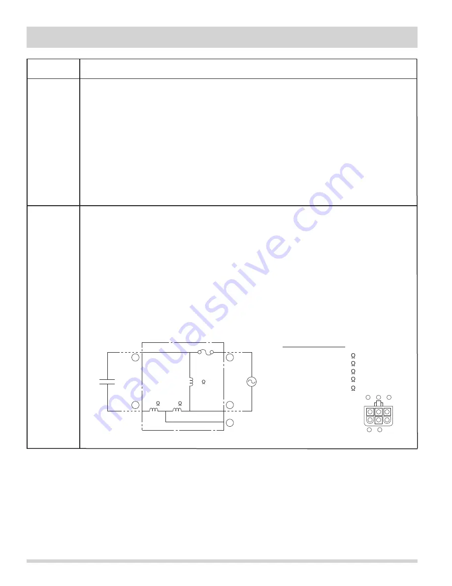
HOOD FAN MOTOR TEST
1. Disconnect power supply cord, and remove outer case.
2. Open the door and block it open.
3. Discharge high voltage capacitor. (See Warnings and Instructions on page 3-1)
4. If the motor does not turn, touch the FAN pad once and check voltage between pins “1” and
“2” (Blue and Black wires) of the 6 pin connector. If 120 Volts appear and the hood capacitor
is good, replace the hood fan assembly. If 120 Volts does not appear, check the motor circuit.
The resistance values of motor terminals are shown below:
5. Reconnect all leads removed from components during testing.
6. Reinstall the outer case (cabinet).
7. Reconnect power supply cord after the outer case is installed.
8. Run oven and check all functions.
R esistance between;
BLU (1) AND YLW (4) = 0 (S horted)
BLK (2) AND YLW (4) = 32
BLU (1) AND BLK (2) = 32
BLK (2) AND WHT (3) = 20
WHT (3) AND R E D (5) = 45
1
2
3
4
5
BLU
BLK WHT
YLW R E D
32
20
45
HOODFAN
CAPACITOR
YLW
R E D
BLU
BLK
1
2
3
WHT
4
5
6-PIN C ONNE C TOR
OF HOOD FAN MOTOR
Summary of Contents for CGMV173KB
Page 2: ......
Page 14: ...Section 2 Operation 2 2 Figure 2 1 Oven Off Condition Figure 2 2 Oven ON Cooking Condition ...
Page 51: ...Section 5 Wiring Diagrams 5 1 Wiring Schematic Oven ON Condition ...
Page 52: ...Section 5 Wiring Diagrams 5 2 Pictorial Component Diagram ...
Page 54: ...Section 5 Wiring Diagrams 5 4 LD1 LD2 LD3 LD4 LD5 Control Board ...


