background image

8

30" DUAL FUEL SLIDE-IN RANGE INSTALLATION INSTRUCTIONS

(Models with an Electric Oven and a Gas Cooktop)

¾”

(1.9 cm)

¾”

(1.9 cm)

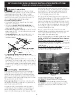
31½”

(81 cm)

Min. 

Cutout 

Width

Formed or tile countertop 

trimmed ¾" (1.9 cm) back at 

front corners of countertop 

opening.

Figure 7

5

 Cabinet Construction

To eliminate the risk of burns or fire by 

reaching over heated surface units, do not have cabinet 
storage space above the range.  If there is cabinet 
storage space above range, reduce risk by installing a 
range hood that projects horizontally a minimum of 5" 
(12.7 cm) beyond the bottom of the cabinet.

Countertop Preparation

• The cooktop sides of the range fit over the cutout 

edge of your countertop.

• If you have a 

square finish (flat) countertop

, no 

countertop preparation is required. Cooktop sides lay 
directly on edge of countertop.

• Formed front-edged countertops 

must have molded 

edge shaved flat 3/4" (1.9 cm) from each front corner 
of opening (Figure 7).

• Tile countertops

 may need trim cut back 3/4"(1.9 

cm) from each front corner and/or rounded edge 
flattened (Figure 7).

6

 Gas Supply – Installation

When shipped from the factory, this unit is designed 
to operate on 4"(10,16 cm) water column (1.0 kPa) 
Natural gas manifold pressure. A convertible pressure 
regulator is connected to the range manifold and MUST 
be connected in series with the gas supply line. To access 
the regulator, remove the drawer.

For proper operation,

 the maximum inlet pressure to 

the regulator should be no more than 14"(35,56 cm) of 
water column pressure (3.5 kPa). 

The inlet pressure to the regulator must be at least 1" 
(.25 kPa) greater than the regulator manifold pressure 
setting. The regulator is set for 4"(10,16 cm) water 
column (1.0 kPa) Natural gas manifold pressure; the inlet 

pressure must be at least 5"(12.60 cm) water column 
(1.25 kPa) Natural gas. For LP/Propane gas, the regulator 
must be set for 10"(25,4 cm) water column (2.5 kPa) 
manifold pressure; the inlet pressure must be at least 
11"(27,9 cm) water column (2.75 kPa).

The supply line should be equipped with an approved 
shutoff valve (see Figure 10). This valve should be located 
in the same room as the range and should be in a 
location that allows ease of opening and closing. Do not 
block access to the shutoff valve. The valve is for turning 
on or shutting off gas to the appliance. Open the shutoff 
valve in the gas supply line. Wait a few minutes for gas 
to move through the gas line.

The gas supply between the shutoff valve and the 
regulator may be connected by rigid piping or by A.G.A./
C.G.A.-approved flexible metallic union-connected 
piping where local codes permit use.

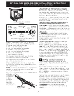
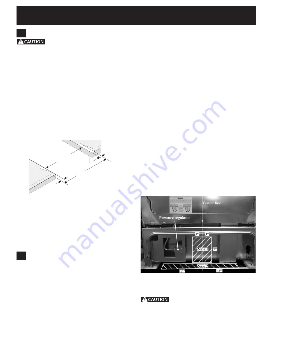
The gas supply piping can be through the back wall 
(Figure 8, zone 1) or through the floor (Figure 8, 
zone 2):
Zone 1 - Through the Back Wall (7" X 6") 

- The best 

place to have your gas line in is between 1" (2.5 cm) and 
8" (20.3cm) from the floor and within 3" (7.6 cm) from 
the center line.

Zone 2 - Through the Floor (~2" X 24") 

- The gas line 

can also come through the floor within 12" (30.5 cm) 
from the center line against the back wall.

Connection to Pressure Regulator

The regulator is already installed on the appliance.

 Do not make the connection too tight. 

The regulator is die cast. Overtightening may crack the 
regulator resulting in a gas leak and possible fire or 
explosion.

Figure 8

• If the existing cutout width is greater than 
  3 0   1 / 1 6 "   ( 7 6 , 4   c m ) ,

  re d u c e   t h e   ¾ "   ( 1 . 9   c m ) 

dimension.

• Countertop must be level.

 Place a level on the 

countertop, first side to side, then front to back. If 
the countertop is not level, the range will not be level. 
The oven must be level for satisfactory baking results. 
Cooktop sides of range fit over edges of countertop 
opening.

Summary of Contents for CPDS3085KF

Page 1: ...a Refer to your serial plate for applicable agency certification 1 2 min 1 4 min WALL 5 Min 12 7 cm Min From Wall Both Sides 30 Min 76 2 cm Min 30 Min 76 2 cm Min see Note 3 18 Min 45 7 cm Min Approx 1 7 8 4 8 cm Grounded Jonction Box or Wall Outlet Should Be Located 8 to 17 20 3 cm to 43 2 cm From Right Cabinet and 2 to 4 5 1 cm to 10 2 cm From Floor Locate Cabinet Doors 1 2 5 cm Min from Cutout ...

Page 2: ...pth when it is open 21 55 25 cm D C A B Door Open Side Panel 1 1 8 2 86 cm FRONT OF CABINET FRef 22 7 8 58 1 cm min 23 1 4 59 05 cm max see Note 4 IMPORTANT To avoid cooktop breakage for cutout width E dimension of more than 30 1 16 76 4 cm make sure the appliance is centered in the counter opening while pushing into it Raise leveling legs at a higher position than the cabinet height see page 3 in...

Page 3: ...oktop Illustration 2 To successfully install the range the initial level height from floor to underside of cooktop frame should be at least 1 16 taller than cabinet sides as measured in step 2 Level the range using the four 4 leveling legs so that the height from the floor to the underside of the metal flange is greater than the tallest cabinet measurement by Metal Flange at least 1 16 see illustr...

Page 4: ...le Home Construction and Safety title 24 HUD part 280 or when such standard is not applicable the Standard for Manufactured Home Installation 1982 Manufactured Home Sites Communities and Setups ANSI Z225 1 NFPA 501A latest edition or with local codes in United States and with CAN CSA Z240 MH in Canada Make sure the wall coverings around the range can withstand the heat generated by the range Befor...

Page 5: ...is permanently grounded Disconnect power to the circuit breaker or fuse box before making the electrical connection This appliance must be connected to a grounded metallic permanent wiring system or a grounding connector should be connected to the grounding terminal or wire lead on the appliance Failure to do any of the above could result in a fire personal injury or electrical shock 1 Factory Con...

Page 6: ...ral White Wire Ground Bare Copper Wire To 240 V Receptacle A User Supplied Strain relief Must Be Installed at This Location Black Wire 1 1 8 2 9cm Dia Direct Connection Hole Punch Out Knockout for 1 3 8 3 5cm Dia Cord Kit Hole NOTE Be sure to remove the supplied grounding strap Figure 4 4 Electrical Connection to the Range U S A Three Conductor Wire Connection to Range If local codes permit connec...

Page 7: ...Connect the 2 black wires together c Connect the 2 red wires together Figure 5 3 Wire Grounded Neutral Electrical System Example Junction Box Cable from Residence Junction Box White Wire U L listed Conduit Connector or CSA listed Cable from Appliance Green or Bare Copper Wire Red Wires Neutral white Wire Black Wires NOTE Be sure to remove the supplied grounding strap Where local codes DO NOT permi...

Page 8: ...re the inlet pressure must be at least 5 12 60 cm water column 1 25 kPa Natural gas For LP Propane gas the regulator must be set for 10 25 4 cm water column 2 5 kPa manifold pressure the inlet pressure must be at least 11 27 9 cm water column 2 75 kPa The supply line should be equipped with an approved shutoff valve see Figure 10 This valve should be located in the same room as the range and shoul...

Page 9: ...ne Leak testing of the appliance shall be conducted according to the manufacturer s instructions Check for leaks After connecting the range to the gas supply check the system for leaks with a manometer If a manometer is not available turn on the gas supply and use a liquid leak detector at all joints and connections to check for leaks Do not use a flame to check for leaks from gas connections Chec...

Page 10: ...n on page 1 9 5 Make sure the four leveling legs are setup higher than the height of the cabinet shown on page 3 9 6 Install the anti tip bracket at this point before placing the range at its final position Follow the installation instructions on page 13 or on the anti tip bracket template supplied with the range 9 7 To provide an optimum installation the top surface of the countertop must be leve...

Page 11: ... for each burner Try each knob separately until all burner valves have been checked 11 4 Adjust the LOW Setting of Surface Burner Valves see Figure 13 a Push in and turn each control to LITE until burner ignites b Quickly turn knob to LOWEST POSITION c If burner goes out readjust valve as follows Reset control to OFF Remove the surface burner control knob insert a thin bladed screw driver into the...

Page 12: ...ide for phone number and address Please call or write if you have inquiries about your range product and or need to order parts Serial Plate Location 11 6 Operation of Oven Elements The oven is equipped with an electronic oven control Each of the functions has been factory checked before shipping However it is suggested that you verify the operation of the electronic oven controls once more Refer ...

Page 13: ... You may also grasp the top rear edge of the range and carefully attempt to tilt it forward to make sure range is properly anchored Figure 16 Leveling Leg Raise Lower CL 18 46 4 cm 28 1 8 71 4 cm 9 1 8 23 2 cm 12 Anti Tip Brackets Installation Instructions To reduce the risk of tipping of the range the range must be secured to the floor by properly installed anti tip brackets and screws packed wit...

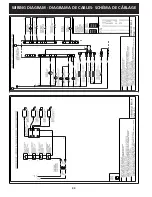
Page 14: ...40 INSTRUCTIONS D INSTALLATION POUR CUISINIÈRE ENCASTRABLE DE 30 À ALIMENTATION MIXTE Modèles avec four électrique et plaque de cuisson à gaz WIRING DIAGRAM Diagrama de cables SCHÉMA DE CÂBLAGE ...

Reviews: