background image

Summary of Contents for FEF450WFDA

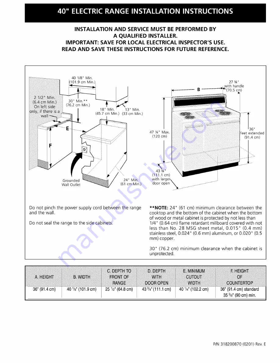
Page 1: ...h the power supply cord between the range and the wall Do not seal the range to the side cabinets NOTE 24 61 cm minimum clearance between the cooktop and the bottom of the cabinet when the bottom of wood or metal cabinet is protected by not lessthan 1 4 0 64 cm flame retardant millboard covered with not less than No 28 MSG sheet metal 0 015 0 4 mm stainless steel 0 024 0 6 mm aluminum or 0 020 0 5...

Page 2: ...ANTI TIP BRACKET S IS ENGAGED Before installing the range in an area covered with linoleum or any other synthetic floor covering make sure the floor covering can withstand heat at least 90 F 32 C above room temperature without shrinking warping or discoloring Do not install the range over carpeting unless you place an insulating pad or sheet of 1 4 6 4 mm thick plywood between the range and carpet...

Page 3: ...ed to the cabinet See Four Conductor Wire Connection to Range on page 4 When a 4 wire receptacle of NEMA Type 14 50R is used see Figure 1 a matching U L listed 4 wire 250 volt 40 ampere range power supply cord pigtail must be used This cord contains 4 copper conductors with ring terminals at the appliance end terminating in a NEMA Type 14 50P plug on the supply end The fourth ground conductor must...

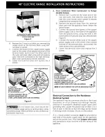
Page 4: ...the ground strap from the terminal block and from the appliance frame Retain the ground screw C Connect the ground wire green of the copper power supply cord to the frame of the appliance with the ground screw using the hole in the frame where the ground strap was removed see Figure 5 D Connect the neutral white wire of the copper power supply cord to the center silver colored terminal of the term...

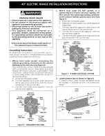
Page 5: ...nnect the power supply B Connect together the 3 wires green bare and white appliance cable wires and the neutral white wire in the junction box C Connect the 2 black wires together then the two red wires together Ground White Wire Cable from PowerSupply _Junction Box Bareor GreenWire Conduit Cablefrom Connector Range or CSAlisted Figure 6 GROUNDED NEUTRAL Where local codes DO NOT permit or if conn...

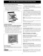
Page 6: ...ack of range will not be flush with the wall the location of the outlet may not allow the range to be positioned against the wall mark on the floor where the back edge of the range will be Place the template on the floor and align sides of template with the iines marked on the fioor Aiign the back of the template with the rear walI or the Iine marked for the rear of the range _Ti_J_ lWhen unpackin...

Page 7: ...ns Bake After setting the oven to 350 F 177 C for baking the lower element in the oven should become red Broil When the oven is set to BROIL the upper element in the oven should become red Clean some models When the oven is set for a self cleaning cycle the upper element should become red during the preheat portion of the cycle After reaching the self cieaning temperature the lower element wiil be...

Page 8: ...1 Unfold paper template and place it ftat on the floor with the back and side edges positioned exactly where the back and sides of range wilI be located when installed Use the diagram below to locate brackets if template is not available 2 Mark on the floor the location of the 4 mounting holes shown on the template For easier installation 3 1 6 4 8 ram diameter pilot holes 1 2 1 3 cm deep can be d...

Page 9: ...abierta _JJJ No pelIizque el cordon eI_ctrico entre Ia estufa y Ia pared No selle Ia estufa a Ios armarios de Iado NOTA Un espacio mfnimo de 24 61 cm entre ia superficie de la estufa y el fondo del armario cuando el fondo det armario de madera o metai esta protegido pot no menos de 1 4 0 64 cm de madera resistente al fuego cubierta pot una lamina met_ilica de MSG n0mero 28 0 015 0 4 ram de acero i...

Page 10: ...n _rea cuyo piso este recubierto con linoleo u otro tipo de piso sint_tico asegt_rese de que estos puedan resistir una temperatura de por Io menos 90 F sobre la temperatura ambiental sin provocar encogimiento deformacion o decoloracion No instale la estufa sobre una alfombra al menos que coloque una plancha de material aislante de por Io menos 1 4 pulgada entre la estufa y la alfombra _Nunca deje ...

Page 11: ...ordon de ser de Tipo SRD o SRDT con un espacio de tirantez tipo U L que debe ser de un m nimo de 4 pies de largo Los calibres m nimos de los conductores para un cordon se suministro de 4 alambres son Circuito de 40 amperios 2 conductores No 8 1 blanco neutral No 10 1 verde de puesta a tierra No 8 Recept_culo de Pared de 4 Alambres 14 50R Figura 2 Recept_culo de Pared de 3 Alambres Juego de Cord6n ...

Page 12: ...exiones de los terminales de la estufa B Quite la banda de puesta a tierra del bloque de los terminales y del marco del artefacto Retenga el tornillo de puesta a tierra C Conecte el alambre de puesta a tierra verde del cordon el_ctrico de cobre al marco del artefacto con el tornillo de puesta a tierra usando el agujero en el marco donde se quit0 el tornillo de puesta a tierra vea figura 5 D Conect...

Page 13: ...mentaciOn B Junte y conecte los tres alambres los alambres de cables verde pelados y neutral blanco del aparato y el alambre neutral blanco en la caja de empalmes C Conecte los dos alambres negros luego conecte los rojos Cable de la fuente de alimentaci6n Alambres __ Alambres blancos negros Alambres rojos de empalmes Alambres Alambres blancos desnudos o Conductor de verdes uni6n listado UL Cable d...

Page 14: ...no estar_ a ras con la pared la ubicaciOn del tomacorriente puede que no permita que la estufa se pegue a ras con la pared marque en el piso donde el borde trasero de la estufa estar Ponga el patron en el piso y alinie los lados del patron con las I neas marcadas en el piso Alinie la parte trasera del patron con la pared trasera o la I nea marcada para la parte trasera de la estufa Mientras se des...

Page 15: ...d verifique el funcionamiento de los controles del homo una vez m_s V_ase el Manual del Usuario para la operaciOn Siga las instrucciones par el Reloj Minutero Cocer Asar CovecciOn algunos modelos y las funciones de limpieza algunos modelos Cocer Bake Despu_s de poner el homo a 350 F 177 C para cocer el element inferior debe ponerse rojo Asar BroiI Cuando est_ puesto para BROIL el elemento superior...

Page 16: ...papel y colOquela plana en el piso con los bordes laterales y el trasero colocados exactamente donde la parte trasera y los lados de la estufa ser_n colocados cuando sea instalada Use el diagrama siguiente para ubicar los soportes si no se dispone de la plantilla 2 Marque en el piso la ubicaciOn de los 4 agujeros de montaje como se muestra en la plantilla Para facilitar la instalaciOn se pueden ta...

Reviews: