IMPORTANT SAFETY NOTICE
The information provided herein is
designed to assist qualified repair
personnel only. Untrained persons
should not attempt to make
repairs due to the possibility of
electrical shock. Disconnect
power cord before servicing.
216804000
SERVICE DATA SHEET
CHEST FREEZER
INSTALLATION
This product is designed for “free standing installation only” and three
inches of clearance must be provided on all sides of the freezer for air
circulation.
The floor or mounting surface should be level and capable of supporting the
weight of the freezer when it is fully loaded.
REFRIGERANT CHARGE AND ELECTRICAL SPECIFICATIONS
Refer to serial plate.
TEMPERATURE CONTROL
14.0°F cut in, 0°F cut-out @ number 1 setting.
PERFORMANCE (Control at number 1 setting)
Room Ambient
70°F
90°F
Freezer Compartment Temperature
5 to 12°F
5 to 12°F
Percent Running Time
30-40%
45-55%
*Wattage Range (Last
1
⁄
3
of cycle)
100-140
110-145
Suction Pressure (Cut-in, cut-out), PSIG
15-0
15-0
High Side Pressure (Last
1
⁄
3
of cycle), PSIG
105-125
155-165
Specifications subject to change without notice.
*For complete performance data by model refer to service manual.
PD642
IMPORTANT
If any green grounding
wires are removed dur-
ing servicing, they
must be returned to
their original position
and properly secured.
Power
Yel
See Diagram
Blk
Wh
Compressor
Temp Warning
Buzzer
Red
Cold Control
Alarm Sensor
Alarm
Off
On
Red
Door
Switch
Interior
Light
Power On
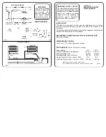
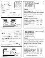
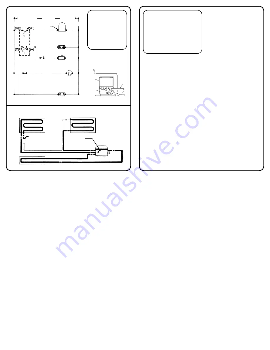
ELECTRICAL CIRCUIT
Red
EC69
Run
Capacitor
Compressor
Controller
Yel
Wh
C10
Condenser
High Side
Process Tube
Drier
Capillary
Evaporator
Low Side
Process Tube
Suction Tube
Discharge
Compressor
SYSTEM SCHEMATIC
WIRING DIAGRAM
SS10