background image

3

40" ELECTRIC RANGE INSTALLATION INSTRUCTIONS

Power Supply Cord Kit

The user is responsible for connecting the power supply 
cord to the connection block located behind the back 
panel access cover.

This appliance may be connected by means of permanent 
"hard wiring" (fl exible armored or nonmetallic shielded 
copper cable), or by means of a power supply cord kit.  
Only a power supply cord kit rated at 125/250 volts 
minimum, 40 amperes and marked for use with ranges 
shall be used. Cord must have 3 conductors (see Figures 
1 and 5).

Mobile homes, new installations, recreational vehicles, or 
areas where local codes do not permit grounding through 
neutral, a 4 conductor power supply cord kit rated at 
125/250 volts minimum, 40 amperes and marked for use 
with ranges should be used (see Figures 2 and 6).

Terminals on ends of wires must either be closed loop 
or open-end spade lugs with upturned ends. Cord must 
have strain relief clamp.

 Risk of fi re or electrical shock may be 

incurred if an incorrect size range cord kit is used, 
the Installation Instructions are not followed, or the 
strain relief bracket is discarded.

If Connecting to a 4-Wire System

This range is manufactured with the ground connected to 
the cabinet. 

The ground must be revised

 so the green 

ground wire of the 4-wire power supply cord is connected 
to the cabinet. See "Four Conductor Wire Connection to 
Range" on page 4.

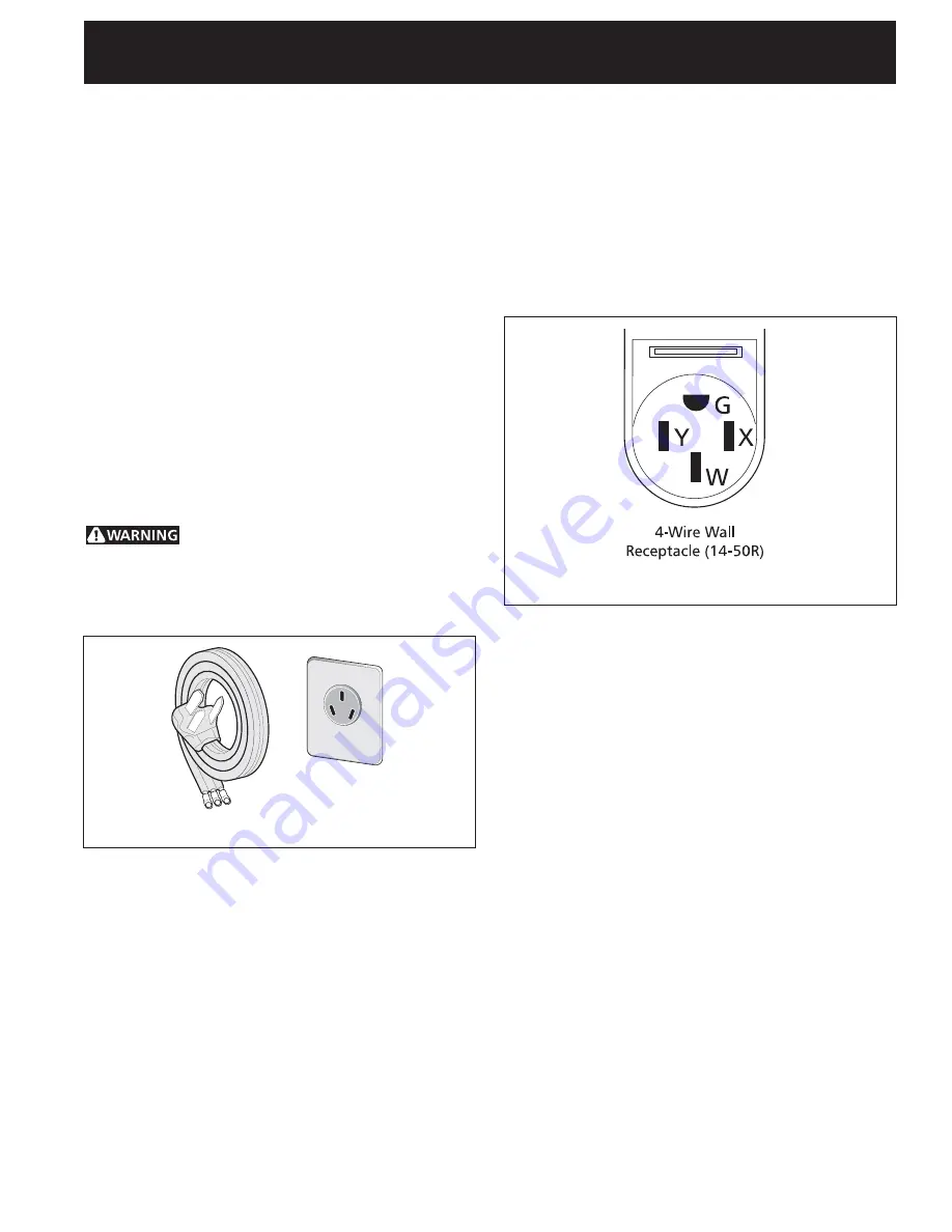
When a 4-wire receptacle of NEMA Type 14-50R is used 
(see Figure 1), a matching U.L.-listed, 4-wire, 250 volt, 
40 ampere range power supply cord (pigtail) must be 
used. This cord contains 4 copper conductors with ring 
terminals at the appliance end, terminating in a NEMA 
Type 14-50P plug on the supply end. The fourth (ground) 

Figure 2

Figure 1

3-Wire Power 

Supply Cord Kit

3-Wire Wall 

Receptacle

Electrical Connection to the Range

This appliance is manufactured with the neutral terminal 
connected to the frame.

1.  Three Conductor Wire Connection to Range


(The 3-conductor cord or cable must be replaced 
with a 4-conductor cord or cable where grounding 
through the neutral conductor is prohibited in mew 
installations, mobile homes, recreational vehicles 
or in other areas where local codes do not permit 
neutral grounding.)


If local codes permit connection of the frame 
grounding conductor to the neutral wire of the 
copper power supply cord (see Figure 4).

A.  Remove the 3 screws at the lower end of the rear 

wire cover, then raise the lower end of the rear 
wire cover (access cover) upward to expose range 
terminal connection block (see Figure 3).

conductor must be identifi ed by a green or green/yellow 
cover and the neutral conductor by a white cover. Cord 
should be Type SRD or SRDT with a U.L.-listed strain relief 
and be at least 4 feet long.

The minimum conductor sizes for the copper 4-wire 
power cord are:
40 ampere circuit
2 No. 8 conductors
1 No. 10 white neutral
1 No. 8 green ground

Summary of Contents for FFEF4015LW

Page 1: ...dle 70 5 cm 36 feet extended 91 4 cm 47 Max 120 cm 43 111 1 cm with larger door open 13 Min 33 cm Min 18 Min 45 7 cm Min 24 Min 61 cm Min 40 1 8 Min 101 9 cm Min 30 Min 76 2 cm Min Grounded Wall Outlet 2 1 2 Min 6 4 cm Min On left side only if there is a wall A HEIGHT B WIDTH C DEPTH TO FRONT OF RANGE D DEPTH WITH DOOR OPEN E MINIMUM CUTOUT WIDTH F HEIGHT OF COUNTERTOP 36 91 4 cm 40 1 8 101 9 cm 2...

Page 2: ...ce is in use As children grow teach them the proper safe use of all appliances Never leave the oven door open when the range is unattended Stepping leaning or sitting on the door s or drawer of this range can result in serious injuries and can also cause damage to the range Do not store items of interest to children in the cabinets above the range Children could be seriously burned climbing on the...

Page 3: ...e Four Conductor Wire Connection to Range on page 4 When a 4 wire receptacle of NEMA Type 14 50R is used see Figure 1 a matching U L listed 4 wire 250 volt 40 ampere range power supply cord pigtail must be used This cord contains 4 copper conductors with ring terminals at the appliance end terminating in a NEMA Type 14 50P plug on the supply end The fourth ground Figure 2 Figure 1 3 Wire Power Sup...

Page 4: ...k B Remove the ground strap from the terminal block and from the appliance frame Retain the ground screw C Connect the ground wire green of the copper power supply cord to the frame of the appliance with the ground screw using the hole in the frame where the ground strap was removed see Figure 5 D Connect the neutral white wire of the copper power supply cord to the center silver colored terminal ...

Page 5: ...ns mobile homes recreational vehicles or in other areas where local codes do not permit neutral grounding A Disconnect the power supply B Connect together the 3 wires green bare and white appliance cable wires and the neutral white wire in the junction box C Connect the 2 black wires together then the two red wires together Figure 6 GROUNDED NEUTRAL 2 Where local codes DO NOT permit or if connecti...

Page 6: ...cabinet opening on floor If back of range will not be flush with the wall the location of the outlet may not allow the range to be positioned against the wall mark on the floor where the back edge of the range will be Place the template on the floor aligning the template centerline with the centerline marked in the cabinet opening Place the back edge of the template against the rear wall or the li...

Page 7: ...g parts for or making inquiries about your range always be sure to include the model and serial numbers and a lot number or letter from the serial plate on your range Before You Call for Service Read the Avoid Service Checklist and operating instructions in your Owner s Guide It may save you time and expense The list includes common occurrences that are not the result of defective workmanship or m...

Page 8: ...he bracket position by placing the template on the floor against the back wall and on the right edge of cabinet Mark the location of the screw holes shown on template A child or adult can tip the range and be killed Verify the anti tip device has been installed to floor or wall Tip Over Hazard Ensure the anti tip device is re engaged to floor or wall when the range is moved Do not operate the rang...

Page 9: ...f the range is level by placing a spirit level on the oven rack Take 2 readings with the spirit level placed diagonally take a reading in one direction and then in the other direction Level the range if necessary by adjusting the leveling legs Anti Tip Bracket Slide range back A N T I T I P B R A C K E T To check if the anti tip bracket is installed properly use both arms and grasp the rear edge o...

Page 10: ...10 40 ELECTRIC RANGE INSTALLATION INSTRUCTIONS ...

Page 11: ...n 45 7 cm Mín 24 Mín 61 cm Mín 40 1 8 Mín 101 9 cm Mín 30 Mín 76 2 cm Mín Tomacomiente de pared puesto a tierra 36 con las patas extendidas 91 4 cm 43 111 1 cm con la puerta grande abierta 2 1 2 Mín 6 4 cm Mín Si hay uno pared el lado izquierdo solamente A ALTURA B ANCHURA C PROFUNDIDAD AL FRENTE DE LA ESTUFA D PROFUNDIDAD CON PUERTA ABIERTA E MÍNIMO DE ANCHO DE ESPACIO RECORTADO F ALTURA DE MOSTR...

Page 12: ...estufa está desatendida No se pare apoye o siente en las puertas o cajones de esta estufa pues puede resultar en serias lesiones y puede también causar daño a la estufa No almacene artículos que puedan interesar a los niños en los gabinetes sobre la estufa Los niños pueden quemarse seriamente tratando de trepar a la estufa para alcanzar estos artículos Los gabinetes de almacenamiento sobre la estu...

Page 13: ...n juego de cordón de estufa de tamaño incorrecto si las instrucciones de instalación no son seguidas o si no se usa el anclaje del cable Figura 1 Juego de Cordón de Suministro Eléctrico de 3 Alambres Receptáculo de Pared de 3 Alambres Figura 2 Receptáculo de Pared de 4 Alambres 14 50R trenza para estufa de 4 alambres de tipo U L de 250 voltios y 40 amperios Este cordón contiene 4 conductores de co...

Page 14: ...de fusibles o cortacircuitos por medio de un cable flexible de cobre blindado o con cubierta no metálica con alambre de puesta a tierra Ubique la caja de empalmes de modo que permita un flojo de 2 o 3 pies en la cuerda para que se pueda mover la estufa si hace falta el servicio No corte el conducto Un conector listado por UL tiene que ponerse en cada extremo del cordón eléctrico en el electrodomés...

Page 15: ... cobre desnudo y los alambres blancos del aparato C Conecte el alambre blanco del aparato con el alambre neutro blanco en la caja de empalmes D Conecte los 2 alambres negros luego los dos alambres rojos E Conecte el alambre desnudo de cobre de puesta a tierra con el alambre de puesta a tierra en al caja de empalmes Alambres negros Alambres blancos Caja de empalmes Cable de la fuente de alimentació...

Page 16: ...n daño a la espalda u otra lesión Si la estufa se va a instalar con un armario a ambos lados marque el centro de la abertura del armario en el piso Si la parte trasera de la estufa no estará a ras con la pared la ubicación del tomacorriente puede que no permita que la estufa se pegue a ras con la pared marque el piso donde estará el borde trasero de la estufa Ponga el patrón en el piso alineando l...

Page 17: ...ación con respecto a su estufa esté siempre seguro de incluir el número de modelo y de serie y el número o letra del lote de la placa de serie de su estufa Antes de Llamar al Servicio Lea la sección Lista de control de averías en su Manual del Usuario Esto le podrá ahorrar tiempo y gastos Esta lista incluye ocurrencias comunes que no son el resultado de defectos de materiales o fabricación de este...

Page 18: ...ar los tornillos Si la montura se va a instalar a en la pared practique un agujero piloto con una inclinación aproximada de 20 hacia abajo Si la montura se va a instalar sobre hormigón para suelos cerámicos practique un agujero de 3 16 con una profundidad de 1 3 4 Los tornillos que se suministran pueden utilizarse en hormigón o madera Para fijar la montura en su sitio utilice un destornillador de ...

Page 19: ...llas interior del horno Tome mínimo 2 lecturas con el nivel coloque el nivel en diagonal para que la cocina este nivelada de atrás hacia adelante si es necesario ajuste las patas niveladoras Para verificar si la fijaciones de anti inclinación está instalado correctamente sostenga el borde trasero de la parte trasera de la estufa usando ambos brazos Intente inclinar la estufa hacia adelante con cui...

Page 20: ...10 INSTRUCCIONES DE INSTALACIÓN PARA LA ESTUFA ELÉCTRICA DE 40 ...

Reviews: