background image

1

ELECTRIC WALL OVEN INSTALLATION INSTRUCTIONS

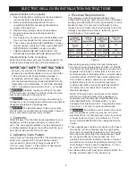
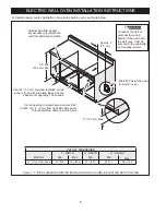
Figure 1

24" SINGLE WALL OVENS (Double ovens see Figure 2)

PN 809017801 Rev. B (19/10)

English – pages 1-8

Español – páginas 9-16

Français -pages 17-24

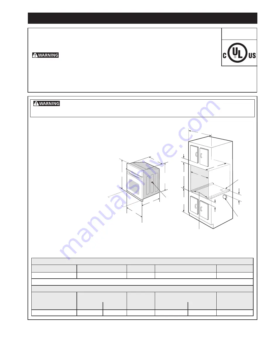
All dimensions are in inches (cm).

Printed in U.S.A.

 Do not remove spacers (if equipped) on the side walls of the built-in oven. These spacers 

center the oven in the space provided. The oven must be centered to prevent excess heat buildup that may 

result in heat damage or fire.

DO NOT INSTALL THIS WALL OVEN IN A BASE CABINET WITH A  COOKTOP ABOVE IT. 

NOTES:

1. Base must be capable of supporting 150 pounds (68 kg)

2. Allow at least 21" (53.3 cm) clearance in front of oven for door 

depth when it is open.

*  Suggested distance from floor is 31" (78.7cm).

  Minimum required distance is 4 ½" (11.4cm).

3. Dimension G (cutout depth) is critical 

to the proper installation of the built-

in oven. If the oven decorative trim 

does not butt against the cabinet, 

verify dimension G to assure it is the 

required depth.

4. For a cutout height greater 

than 28

7

/

8

"


(73.3 cm) add one 

2"(5 cm) wide wood shim of 

appropriate height to each 

side of the opening under the 

appliance side rails.

INSTALLATION AND SERVICE MUST BE PERFORMED BY A QUALIFIED INSTALLER.

IMPORTANT: SAVE FOR LOCAL ELECTRICAL INSPECTOR'S USE. 

READ AND SAVE THESE INSTRUCTIONS FOR FUTURE REFERENCE.

 FOR YOUR SAFETY: Do not store or use gasoline or other flammable vapors 

and liquids in the vicinity of this or any other appliance.

Your new wall oven has been designed to fit a limited variety of cutout sizes to make the job 

of installing easier. The first step of your installation should be to measure your current cutout 

dimensions and compare them to the cutout dimensions chart below for your model. You may 

find little or no cabinet work being necessary.

United States 

and Canada

PRODUCT DIMENSIONS

MODEL

A

B

C

D

24" (61 cm) Wall Oven

23

7

/

8

 (60.6)

30

3

/

4

 (78.1)

21

3

/

4

 (55.2)

25

3

/

16

 (64)

CUTOUT DIMENSIONS AND CABINET WIDTH

F

G (Min.)

H. Standard Height


(**Others, see note 4)

I

MODEL

Min.

Max.

Min. 

Max

.

24" (61 cm) Wall Oven

22 (55.9)

22

1

/

2

 (57.2)

23

1

/

2

 (59.7)

28 (71.1)

28

7

/

8

 (73.3)

24 (61) Min

I

H

F

G

B

A

D

C

2" (5 cm) Wide Wood 

Spacer if Needed

Spacer

Electrical

Junction Box

Hole for 

Cord

Door Open

(see note 2)

3"


(7.6 cm)

Max.

2"


(5.1 cm) Max.

31" 

(78.7cm)

1

1

/

2

(3.8cm)

28" 

(71.1 cm)

Summary of Contents for FFEW2426UB

Page 1: ... one 2 5 cm wide wood shim of appropriate height to each side of the opening under the appliance side rails INSTALLATION AND SERVICE MUST BE PERFORMED BY A QUALIFIED INSTALLER IMPORTANT SAVE FOR LOCAL ELECTRICAL INSPECTOR S USE READ AND SAVE THESE INSTRUCTIONS FOR FUTURE REFERENCE FOR YOUR SAFETY Do not store or use gasoline or other flammable vapors and liquids in the vicinity of this or any othe...

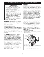
Page 2: ... 1 Place shims of appropriate height beneath the oven side rails 3 Electrical Requirements This appliance must be supplied with the proper voltage and frequency and connected to an individual properly grounded branch circuit protected by a circuit breaker or fuse To know the circuit breaker or fuse required by your model see the serial plate to find the wattage consumption and refer to table A to ...

Page 3: ...n 1996 NEC mobile home recreational vehicles where local code do not permit grounding trough the neutral white wire or in Canada disconnect the white and green lead from each other and use ground lead to ground unit in accordance with local codes connect neutral lead to branch circuit neutral conductor in usual manner see Figure 3 If your appliance is to be connected to a 3 wire grounded junction ...

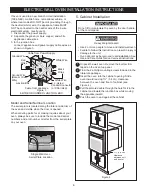
Page 4: ... GROUNDED JUNCTION BOX Cable from Power Supply White Wire Junction Box Cable from appliance White Wire Black Wires Red Wires Ground Wire Ground Wire Bare or Green Wire U L Listed Conduit Connector or CSA listed Heavy Weight Hazard Use 2 or more people to move and install wall oven Failure to follow this instruction can result in injury or damage to the unit Oven doors may be removed to aid install...

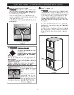
Page 5: ...ay cause personal injury and may damage cabinetry or the appliance Screws to attach the bottom trim are supplied with the oven Oven door may be removed to aid bottom trim installation A Place the top of the bottom trim over the side trim tabs on each side of the oven below the oven door B Attach the trim using the provided screws see Figure 6 Tip Over Hazard A child or adult can tip the oven and b...

Page 6: ... to route armored cable to junction box 208 240 Volt junction box for built in oven Approx 3 7 5 cm Cabinet side filler panels are necessary to isolate the unit from adjoining cabinets To reduce the risk of personal injury and tipping of the wall oven the wall oven must be secured to the cabinet s by mounting screws 5 12 7 cm Max For typical under counter installation of an electric built in oven ...

Page 7: ...vice Checklist and the Operating Instructions in your Use and Care Guide It may save you time and expense The list includes common occurrences that are not the result of defective workmanship or materials in this appliance Refer to your Use and Care Guide for service phone numbers 6 Leveling the Wall Oven 1 Install an oven rack in the center of the upper oven see Figure 8 2 Place a level on the ra...

Page 8: ...8 ELECTRIC WALL OVEN INSTALLATION INSTRUCTIONS NOTES ...

Page 9: ...ara su instalación debe de ser el de medir las dimensiones de la apertura y compararlas con las que se indican en el cuadro de dimensiones del hueco de la figura 1 Posiblemente encontrará que algún trabajo de carpintería será necesario LA INSTALACIÓN Y EL SERVICIO DEBEN SER EFECTUADOS POR UN INSTALADOR CALIFICADO IMPORTANTE GUARDE ESTAS INSTRUCCIONES PARA USO DEL INSPECTOR LOCAL DE ELECTRICIDAD LE...

Page 10: ...el caso del horno único de pared ver la Figura 1 Colocar las cuñas de altura apropiada debajo de los rieles laterales del horno 3 Requerimientos Eléctricos Se debe proveer el voltaje y la frecuencia apropiados a este electrodoméstico y conectarse a un circuito individual correctamente puesto a tierra protegido por un interruptor o un fusible Para conocer el interruptor o fusible que requiere su mo...

Page 11: ...erminal de puesta a tierra o el alambre conductor en al aparato No utilice el suministro de gas para hacer la puesta a tierra La falta de cualquiera de las instrucciones mencionadas podría resultar en un incendio choque eléctrico o lesiones personales Figura 2 CAJA DE EMPALMES DE 3 ALAMBRES PUESTA A TIERRA Cable desde el suministro de energía Cable de la estufa Alambre desnudo Alambre rojos Caja d...

Page 12: ...MBRES PUESTA A TIERRA Alambre desnudo Cable desde el suministro de energía Alambre verde o desnudo Cable de la estufa Caja de empalmes Conductor de unión listado UL o CSA Alambre blanco Alambre rojos Alambre negros Alambre blanco Peligro de Peso Pesado Use 2 personas o más para mover e instalar el horno de pared Si no cumple con esta instrucción puede resultar en lesiones personales o daños al hor...

Page 13: ...causar lesiones física tambien puede dañar el gabinete o puede causar daños el aparato electrodoméstico Los tornillos para instalar la guarda de seguridad inferior son proporcionados con el horno Remover la puerta del horno para ayudar a la instalación de el borde inferior A Colocar la guarda de seguridad inferior sobre las pestañas de cada lado del horno de bajo de la puerta del horno B Fijar la ...

Page 14: ...fondo del contrachapado a 2 5 cm del lado derecho del panel llenador para poder encaminar el cable a la caja de empalme 208 240 caja de empalme para hornos de pared Para reducir el riesgo de lesiones personales y inclinación del horno de pared éste debe asegurarse a los gabinetes mediante soportes de montaje F G H 36 Min 91 4 cm Min Approx 3 7 5 cm Los paneles de relleno laterales del gabinete son...

Page 15: ...l de Averías en su Manual del Usuario Esto le podrá ahorrar tiempo y gastos Esta lista incluye ocurrencias comunes que no son el resultado de defectos de materiales o fabricación de este artefacto Lea la garantía y la información sobre el servicio en su Manual del Usuario para obtener el número de teléfono gratuito IMPORTANTE Un ventilador ubicado dentro de la parte trasera superior arriba del hor...

Page 16: ...16 INSTRUCCIONES DE INSTALACIÓN PARA EL HORNO ELÉCTRICO DE PARED NOTAS ...

Page 17: ... ET L ENTRETIEN DOIVENT ÊTRE EFFECTUÉS PAR UN INSTALLATEUR QUALIFIÉ IMPORTANT CONSERVEZ POUR L INSPECTEUR D ÉLECTRICITÉ LOCAL LISEZ ET CONSERVEZ CES INSTRUCTIONS POUR RÉFÉRENCES ULTÉRIEURES POUR VOTRE SÉCURITÉ N entreposez pas ou n utilisez pas d essence ou d autres produits inflammables à proximité de cet appareil ou de tout autre appareil électroménager Votre nouveau four encastré a été conçu po...

Page 18: ... la hauteur du découpage excède la dimension 275 8 70 2 cm pour un four encastré simple voir la figure 1 Placez l entretoise de hauteur appropriée de chaque côté de l ouverture sous l appareil 3 Exigences électriques Ces appareils doivent être branchés à une alimentation possédant la tension et la fréquence appropriées Ils doivent être connectés à un circuit dédié correctement mis à la terre et pr...

Page 19: ...anchez pas l appareil au circuit électrique tant qu il ne sera pas mis à la terre correctement et en permanence Coupez l alimentation à la boîte de jonction avant de faire les raccords électriques Cet appareil doit être connecté à un circuit permanent électrique métallique et mis à la terre ou à un connecteur de mise à la terre qui doit être branché à la borne ou au fil de mise à la terre de l app...

Page 20: ...es ou demande de renseignement au sujet de votre appareil assurez vous d inclure les numéros de modèle et de série ainsi que le numéro ou lettre de lot de la plaque signalétique de votre four Risque de lourde charge Soyez 2 personnes ou plus pour installer ou déplacer l appareil Des blessures ou des dommages à l appareil peuvent survenir si vous ne suivez pas cette instruction La porte du four peu...

Page 21: ...r l installation d une garniture inférieure A Placez le dessus de la moulure inférieure par dessus les pattes des moulures latérales de chaque côté du four sous la porte du four B Fixer la moulure en utilisant les vis fournies voir Figure 6 Risquedebasculement Trous de montage du dispositif anti renverse ment Pour une installation adéquate du dispositif anti renverse ment reportez vous aux instruc...

Page 22: ... four encastré Utilisez un contre plaqué de 1 9 cm d épaisseur monté sur deux solives et à égalité avec le coup de pied La base doit pouvoir supporter 150 lbs 68 kg Découpez une ouverture de 9 X 9 23 cm X 23 cm à 2 5 cm du côté droite du plancher pour la sortie du câble armé de l appareil vers la boîte de jonction Il faut fermer les côtés de l habitacle par des panneaux de bois pour isoler l appar...

Page 23: ...tion dans votre Manuel d utilisation et d entretien Vous sauverez probablement du temps et de l argent La liste contient les incidents ordinaires ne résultant pas de défectuosités dans le matériel ou la fabrication de cet appareil Pour obtenir notre adresse et notre numéro de téléphone sans frais référez vous à votre Manuel d utilisation et d entretien 6 Mise à niveau du four encastré 1 Installez ...

Page 24: ...24 INSTRUCTIONS D INSTALLATION POUR FOUR ENCASTRÉ ÉLECTRIQUE NOTES ...

Reviews: