background image

Installation Instructions 


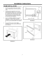
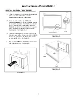
FRAME INSTALLATION 


Foot


1. 

Place the oven adjacent to the wall or cabinet 
opening. Plug the power cord into the electrical 
outlet. 
 

2. 

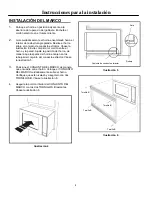
Carefully guide the assembled oven into the 
prepared opening. Slide the oven on the Exhaust 
Duct Assembly. See Illustration 4. Avoid pinching 
the cord between the oven and the wall. Adjust 
the position of the oven so that the feet of the 
oven are fitted into the recesses of the Exhaust 
Duct Assembly. See Illustration 5.  
 

3. 

Position the FRAME ASSEMBLY to be square 
with the oven. Carefully place the FRAME 
ASSEMBLY on the oven. Check that it is level and 
then secure with two SCREWS B. See Illustration 
6.  
 

Races


Exhaust Dust Assembly


Illustration 5


4. 

Secure the bottom portion of the FRAME 
ASSEMBLY with the two remaining SCREWS B. 
See Illustration 6. 


Screw B


Screw B


Screw B


Screw B


Illustration 6


Illustration 4


Summary of Contents for MWTK(P)27K

Page 1: ...used in handling and installation to avoid the possibility of injury Do not remove permanently affixed labels warnings or plates from the product This may void the warranty IMPORTANT PLEASE READ AND FOLLOW THIS BUILT IN KIT IS DESIGNED FOR USE ONLY WITH ELECTROLUX MICROWAVE OVENS SPECIFYING BUILT IN KIT MWTK P 27K OR MWTK P 30K ON THE RATING LABEL ON THE LEFT SIDE WALL OF THE MICROWAVE OVEN CAVITY...

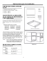
Page 2: ...PM0209KF See Illustration 1 for proper location when building in above a wall oven Carefully follow both the wall oven installation instructions and Electrolux s Built in Kit instructions If building over a wall oven be sure the clearance between the wall oven and the microwave oven is a minimum of 3 inches NOTE Trim Kit and microwave can only be built in over an electric self clean or non self cl...

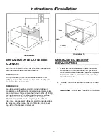
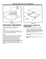
Page 3: ...The floor should be level for proper operation of the oven Be sure to check the local building code as it may require that the opening be enclosed with side ceiling and rear partition The proper functioning of the oven does not require the enclosure Flanges Screw A Exhaust Dust Assembly Screw A Illustration 3 EXHAUST DUCT ASSEMBLY 1 Place the Exhaust Duct in the opening When the Exhaust Duct Assem...

Page 4: ...e wall Adjust the position of the oven so that the feet of the oven are fitted into the recesses of the Exhaust Duct Assembly See Illustration 5 3 Position the FRAME ASSEMBLY to be square with the oven Carefully place the FRAME ASSEMBLY on the oven Check that it is level and then secure with two SCREWS B See Illustration 6 Races Exhaust Dust Assembly Illustration 5 4 Secure the bottom portion of t...

Page 5: ...tinée au consommateur Conserver ces instructions pour référence ultérieure Niveau de compétences L installation de cet appareil exige des compétences élémentaires en mécanique et en électricité IMPORTANT LIRE ET SUIVRE CES INSTRUCTIONS CET ENSEMBLE DE GARNITURE À ENCASTREMENT EST DESTINÉ UNIQUEMENT AUX FOURS À MICRO ONDES ELECTROLUX EXIGEANT UNE TELLE GARNITURE LA MENTION MWTK P 27K OU MWTK P 30K ...

Page 6: ... adéquat d un appareil encastré au dessus d un four mural Suivre avec soin les instructions d installation du four mural et celles de l appareil encastré Electrolux Si l appareil est encastré au dessus d un four mural s assurer qu il y a un dégagement d au moins 7 6 cm 3 po entre la paroi du four et le four à micro ondes REMARQUE L ensemble de garniture d encastrement et le four à micro ondes doiv...

Page 7: ...cher doit être de niveau de manière à assurer le bon fonctionnement du four Vérifier votre code du bâtiment local car il pourrait exiger que des cloisons latérales supérieure et inférieure soient construites dans la niche La niche n a pas besoin d être cloisonnée pour que le four fonctionne correctement Brides Vis A Conduit d évacuation Vis A Illustration 3 MONTAGE DU CONDUIT D ÉVACUATION 1 Placer...

Page 8: ...ordon se coince entre le four et le mur Régler la position du four de manière à ce que les pieds s emboîtent dans les gorges du conduit d évacuation Voir l illustration 5 Gorge Conduit d évacuation 3 Positionner le CADRE de manière à ce qu il soit d équerre avec le four Poser avec soin le CADRE sur le four Vérifier qu il est de niveau et le fixer avec deux VIS B Voir l illustration 6 Illustration ...

Page 9: ...ivel de habilidad La instalación de este artefacto requiere habilidades mecánicas y eléctricas básicas IMPORTANTE POR FAVOR LEA Y CUMPLA ESTE KIT PARA INSTALACIÓN EMPOTRADA ESTÁ DISEÑADO PARA SU USO SOLAMENTE CON HORNOS DE MICROONDAS DE MARCA ELECTROLUX QUE ESPECIFIQUEN EL USO DE UN KIT PARA INSTALACIÓN EMPOTRADA MWTK P 27K o MWTK P 30K EN LA ETIQUETA DE VALORES NOMINALES UBICADA EN LA PARED IZQUI...

Page 10: ...rno se va a empotrar sobre un horno de pared Siga las instrucciones para la instalación del horno de pared y las instrucciones del kit para instalación empotrada de Electrolux cuidadosamente Si se va a empotrar sobre un horno de pared cerciórese de que la separación vertical entre el horno de pared y el horno de microondas sea de por lo menos 3 pulgadas 7 5 cm NOTA El kit de marco para instalación...

Page 11: ...ivelado para el funcionamiento correcto del horno Asegúrese de consultar el código de construcción local ya que puede requerir que la abertura esté encerrada por un tabique divisorio lateral superior y posterior No se requiere el recinto cerrado para el funcionamiento correcto del horno Bridas Tornillo A Conjunto de conducto extractor Tornillo A Ilustración 3 CONJUNTO DE CONDUCTO EXTRACTOR 1 Coloq...

Page 12: ... la pared Ajuste la posición del horno de manera que las patas del horno encajen en los rebajes del conjunto del conducto extractor Véase la ilustración 5 Rebaje Conjunto de conducto extractor 3 Posicione el CONJUNTO DEL MARCO de manera que encuadre con el horno Coloque el CONJUNTO DEL MARCO cuidadosamente sobre el horno Verifique que esté nivelado y asegúrelo con dos TORNILLOS B Véase la ilustrac...

Reviews: