background image

|  

8


User Instructions Low Temperature Freezers Model GLE

Livøvej 22 - 8800 Viborg - Tlf. 86 61 34 11 - www.frigor.dk

User Instructions  Low Temperature Freezers Model UNI/LT

8

PARAMETERS

NOTE: the parameters preceded by dots are 
in the Hidden Menu.
REGULATION

Hy Differential:

 (0,1 ÷ 25,5°C / 1÷255 °F) Inter-

vention differential for set point. Compressor 
Cut IN is Set Point Plus Differential (Hy). Com-
pressor Cut OUT is when the temperature 
reaches the set point.
• 

LS Minimum set point: 

(- 50°C÷SET-58°F÷ 

   SET): Sets the minimum acceptable value    
   for the set point.
• 

US Maximum set point:

 (SET÷110°C/ SET÷ 

   230°F). Set the maximum acceptable     


   value for set point.

Ot Thermostat probe calibration:

 (-12.0÷ 

12.0°C; -120÷120°F) allows to adjust possible 
offset of the thermostat probe.
• 

OdS Outputs activation delay at start up:


   (0÷255min) This function is enabled at the  
   initial start up of the instrument and inhibits  
   any output activation for the period of     
   time set in the parameter.

AC Anti-short cycle delay:

 (0÷50 min) mini-

mum interval between the compressor stop 
and the following restart.
• 

CCt Compressor ON time during continu 


   ous cycle:

 (0.0÷24.0h; res. 10min) Allows  


   to set the length of the continuous cycle:  
   compressor stays on without interruption 
   for the CCt time. Can be used, for in- 


   stance, when the room is filled with new  


   products.
• 

COn Compressor ON time with faulty  


   probe:

 (0÷255 min) time during which 

   the compressor is active in case of fauly  


   thermostat probe. With COn=0 compressor  
   is always OFF.
• 

COF Compressor OFF time with faulty         

   probe:

 (0÷255 min) time during which the  

   compressor is OFF in case of faulty thermo 
   stat probe. With COF=0 compressor is   


   always active.

CH Type of action:

 CL = cooling; Ht = heating.

DISPLAY
• 

CF Temperature measurement unit:


°C

=Celsius; 

°F

=Fahrenheit. 

WARNING: 

When  

   the measurement unit is changed the SET  


   point and the values of the parameters Hy,  
   LS, US, Ot, ALU and ALL have to be checked  
   and modified if necessary).

rES Resolution (for °C):

 (in = 1°C; dE = 0.1 °C) 

allows decimal point display.
DEFROST

IdF Interval between defrost cycles:

 (0÷120h) 

Determines the time interval between the 
beginning of two defrost cycles.

MdF (Maximum) length for defrost:

 (0÷255min) 

When 

P2P = n

, (not evaporator probe: timed 

defrost) it sets the defrost duration, when 

P2P 

= y

 (defrost end based on temperature) it sets 

the maximum length for defrost.
• 

dFd Temperature displayed during defrost:

 (

rt


   = real temperature; 

it

 = temperature at de 


   frost start; 

SEt

 = set point; 

dEF

 = “dEF” label)

• 

dAd MAX display delay after defrost:


   (0÷255min). Sets the maximum time
   between the end of defrost and the restart 


   ing of the real room temperature display.
ALARMS
• 

ALC Temperature alarms configuration:


   (Ab; rE) Ab= absolute temperature: alarm  
   temperature is given by the ALL or ALU
   values. 

rE

 = temperature alarms are re 


   ferred to the set point. Temperature
   alarm is enabled when the temperature  


   exceeds the “SET+ALU” or “SET-ALL”
   values.

ALU MAXIMUM temperature alarm: 

(SET÷110°C; SET÷230°F) when this tempera-
ture is reached the alarm is enabled, after 
the “ALd” delay time.

ALL Minimum temperature alarm:

 (-50.0 ÷ 

SET°C; -58÷230°F when this temperature is 
reached the alarm is enabled, after the
“ALd” delay time.
• 

ALd Temperature alarm delay: 

(0÷255 min)  

   time interval between the detection of an  
   alarm condition and alarm signalling.

• 

dAO Exclusion of temperature alarm at  


   startup:


(from 0.0 min to 23.5h) time interval  

   between the detection of the tempera- 


   ture alarm condition after instrument  
   power on and alarm signalling.

SECOND RELAY AND DIGITAL INPUT

 tbA Alarm relay silencing (with oAC=ALr):

   (

n

= silencing disabled: alarm relay stays  


   on till alarm condition lasts, 

y

 =silencing  


   enabled: alarm relay is switched OFF by  


   pressing a key during an alarm).

Summary of Contents for GLE

Page 1: ...User Instructions Low Temperature Freezers Model GLE Livøvej 22 8800 Viborg Tlf 86 61 34 11 www frigor dk Low Temperature Freezers Model GLE User Instructions mODEL gle ...

Page 2: ...n order to avoid any injuries contact the sup plier for further information Never put naked flames or other igni tion sources inside the appliance Never touch the freezers interior or products in the freezer when the freezer is operating Use gloves or alike in order to avoid injuries frost bite Keep the key to the appliance away from the appliance and out of the reach of children 3 Connection to th...

Page 3: ...In order for the freezer to work to its maxi mum efficiency the cabinet should be de frosted when a approx 2mm thick ice layer has formed inside the cabinet The ice layer is easily removed with a plastic or wooden scraper Never use a sharp metal object which might will cause damage to the inner liner The defrosting frequency is determined mainly by two factors the usage pattern number of lid opening...

Page 4: ...safe storage of sensitive products In some situations the GLE freezer is also used for other applications like in laborato ries for different low temperature test Depending on the actual situation it might be necessary to change the controllers off set value in order to get a correspondence between the reading on the display and the actual temperature inside the cabinet The factory setting is an offs...

Page 5: ...e separated and far enough from each other without crossing or intertwining In case of applications in industrial environments the use of mains filters our mod FT1 in parallel with inductive loads could be useful GENERAL DESCRIPTION Model XR30C format 32 x 74 mm is a digital termostat with off cycle defrost designed for refrigeration applications at normal temper ature It provides two relay outputs ...

Page 6: ...taken place To see the kind of alarm the max min reached temperature and alarm duration do as follows 1 Push the Up or Down key 2 On the display the following mes sage is shown HAL for high temperature alarm LAL fot the minimum allarm followed by the Maximum mini mum temperature Then the tiM tiMe message is displayed followed by the Dura tion in h mm 3 Then the instrument displays the temperature ...

Page 7: ...eep pressed the Set n for more than 7s The Pr2 label will be displayed immediately fol lowed from the HY parameter NOW YOU ARE IN THE HIDDEN MENU 3 Select the required parameter 4 Press the SET key to display its value Now only the LED is blinking 5 Use o or n to change its value 6 Press SET to store the new value and move to the following parameter To exit Press SET o or wait 15s without pressing...

Page 8: ...elsius F Fahrenheit WARNING When the measurement unit is changed the SET point and the values of the parameters Hy LS US Ot ALU and ALL have to be checked and modified if necessary rES Resolution for C in 1 C dE 0 1 C allows decimal point display DEFROST IdF Interval between defrost cycles 0 120h Determines the time interval between the beginning of two defrost cycles MdF Maximum length for defrost...

Page 9: ...input is program mable in five different configurations by the i1F parameter DOOR SWITCH INPUT i1F dor It signals the door status and the corre sponding relay output status through the odc parameter no Fan normal any change CPr F_C Compressor OFF Since the door is opened after the delay time set through parameter did the door alarm is enabled the display shows the mes sage dA and the regulation resta...

Page 10: ... suitable external relay PROBE CONNECTION The probes shall be mounted with the bulb upwards to prevent damages due to casual liquid infiltration It is recommended to place the thermostat probe away from air streams to correctly measure the average room temperature Place the defrost termination probe among the evaporator fins in the coldest place where most ice is formed far from heaters or from the ...

Page 11: ... Housing self extinguishing ABS Case XR30C frontal 32x74 mm depth 60mm Mounting XR30C panel mounting in a 71x29mm panel cut out Protection IP20 Frontal protection IP65 with frontal gasket RG C optional Connections Screw terminal block 2 5 mm2 wiring Power supply according to the model 12Vac dc 10 24Vac dc 10 230Vac 10 50 60Hz 110Vac 10 50 60Hz Power absorption 3VA max Display 3 digits red LED 14 2...

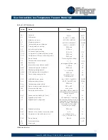
Page 12: ...alarm at start up Alarm relay silencing 2nd relay configuration Second relay polarity oA1 ALr Digital input polarity Digital input configuration Digital input delay Number of activation of pressure switch Compressor status with open door Kind of probe Software release Map code Label Name Range C F 3 0 37 2 0 4 50 0 58 110 230 0 0 0 1 0 0 15 30 CL ºC ºF dE 8 20 it 30 Ab LS US 0 1 25 5ºC 1 255ºF 50º...

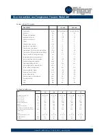
Page 13: ...p Probe selection N A N A Label Set Hy LS US Ot Ods AC CCt COn COF CH CF ldF Mdf dFd dAd Alc ALU ALL Ald dAo PbC Rel Ptb Dixell XR30C 115 volt Setting Celcius 45 3 50 0 0 1 3 0 60 5 CL C 120 0 Set 1 Ab 36 50 120 24 Ptc 3 84 Setting Farenheit 45 3 58 0 0 1 3 0 60 5 CL F 120 0 Set 0 Ab 33 58 120 24 Ptc 3 84 230 volt Ambient temperature Gross volume Gross volume Height on feet Height with open lid Wi...

Page 14: ... Freezers Model GLE Livøvej 22 8800 Viborg Tlf 86 61 34 11 www frigor dk User Instructions Low Temperature Freezers Model UNI LT 14 Wiring diagrams Censor Power supply 230V 50 60 HZ Power supply 230V 50 60 HZ Censor GLE 10 20 30 40 GLE 50 ...

Reviews: