background image

17 

7425MUM661 

Model: CWB FC 

- Use and Maintenance Manual


Rev02 


ELECTRONIC CONTROLLER  

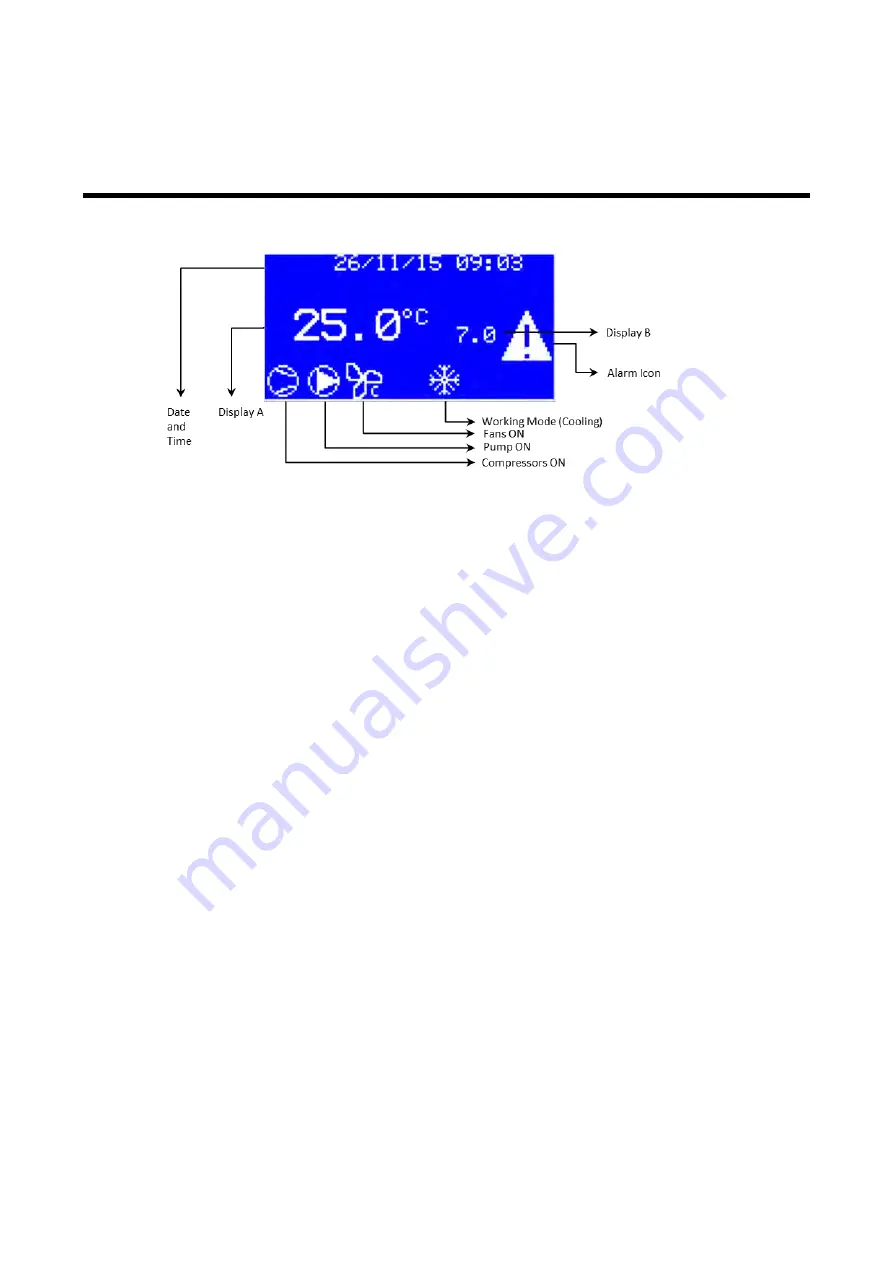
The electronic controller shows a series of icons representing chillers main components: 


Electronic controller 

It manages: 

  The functioning of the compressors to ensure that the water produced has a constant 

temperature;  

  The speed of the fans;  

  The functioning of the pump; 

  The prevention of the high-pressure alarm. 

 
Displays: 

  The state of the unit;  

  The state of the compressors;  

  The state of the fans;  

  The state of the pump; 

  The temperature set point (standard factory setting) (display B); 

  The temperature of the water produced (standard factory setting) (display A);  

  All digital and analogue inputs and outputs (parameters navigation); 

  All the alarms that can occur. 

Summary of Contents for PURESTREAM CWB FC

Page 1: ...WATER CHILLER Model CWB FC Free Cooling User and Maintenance Manual BY FRIULAIR CHILLERS PURESTREAM ...

Page 2: ...Editions Record Code Revision Edition Notes 7425MUM661 02 09 2019 Original instructions ENGLISH ...

Page 3: ...ve any problems or need more information The product identification plate located on the side of the chiller contains all essential information about the machine Warranty conditions The warranty is valid for 12 months from the machine being powered up and no longer than 14 months from the delivery date Any part which is recognised as being faulty at source shall be repaired or replaced free of cha...

Page 4: ...es 11 3 4 Water connections 12 3 4 1 Recommended water system 12 3 4 2 Use of ethylene glycol as a winter anti freeze 13 3 4 3 Charging the water circuit 14 3 5 Electrical connections 14 3 5 1 Remote on off switch and alarm indicators 14 4 PRELIMINARY CHECKS AND START UP 15 4 1 Preliminary checks and preparation for the first start up 15 4 2 Start up 15 4 2 1 Start up under critical conditions 16 ...

Page 5: ...26 6 2 Low water temperatures 32 F 0 C 26 6 3 Neutral zone regulation based on outlet water temperature Standard 27 6 3 1 Recommended setting for operating with low water temperatures 28 7 SAFETY DEVICES 29 7 1 Calibration of the safety devices and type of rearm 29 7 2 Resetting the high pressure pressure switch 30 8 OPERATING LIMITS 31 9 MAINTENANCE INSPECTIONS AND PERIODIC CHECKS 34 10 TROUBLESH...

Page 6: ...ns that could be fatal Follow the instructions provided meticulously Risk of danger component or system under pressure Risk of danger component or system that can reach high temperatures during operation Risk of danger it is absolutely forbidden to use water to extinguish fires near or on the chiller Risk of danger it is absolutely forbidden to operate the machine with the panel open Service that ...

Page 7: ...be re connected to the electrical power supply These chillers contain R410A refrigerant fluids Service of the refrigerant circuit must be performed by specialized personnel using proper tools Any modifications to the machine or related operating parameters not previously verified and authorised by the Manufacturer may be hazardous and will invalidate the guarantee Do not use water to extinguish fi...

Page 8: ...the manufacturer s name data plate Do not solder on the exchangers or refrigerant fluid pipes Do not install the equipment in insufficiently ventilated rooms areas exposed to sources of heat or near inflammable substances During operation the equipment must not be subjected to vibrations that could cause fatigue failures Keep the documentation attached to the equipment user manual declaration of c...

Page 9: ... in such a way as to maintain the constancy of the superheating of the gas exiting to the evaporator under its various working conditions and thus ensures that the flow of gas entering the compressor contains no liquid Thanks to these components the vapour compression cycle works as follows the refrigerant liquid evaporates in the evaporator chilling the water the refrigerant vapours are then aspi...

Page 10: ...valve grants the correct operation of the machine 2 4 FANS The fans force air through the condenser s fins to remove the heat from the condensation of the refrigerant gas thus limiting the pressure inside the condenser CWB FC chillers use external rotor axial fans with thermal protection inside the motor winding 2 5 CONDENSATION CONTROL When the temperature of the surrounding air drops the cooling...

Page 11: ... safety valve 8 Compressor 2 High pressure switch 9 Suction temperature probe 3 High pressure transducer 10 Low pressure refrigerant gauge 4 Condenser 11 High pressure refrigerant gauge 5 Low pressure transducer 12 Water gauge 6 Liquid refrigerant solenoid valve 13 Air temperature probe 7 Refrigerant filter 14 Fan ...

Page 12: ...25MUM661 Model CWB FC Use and Maintenance Manual Rev02 15 Liquid sight glass 19 Pump 16 Electronic thermostatic valve 20 Three way valve 17 Water differential pressure switch 21 Valve actuator 18 Evaporator ...

Page 13: ...25MUM661 Model CWB FC Use and Maintenance Manual Rev02 22 Electrical panel cut off switch 25 Water inlet 23 Electrical control panel 26 Water outlet 24 Power input cable openings 27 Free cooling coils drain ...

Page 14: ...unit near the installation site and unpack it Always keep the chiller vertical turning it upside down can irreparably damage several parts of the unit Handle with care Violent falls can cause irreparable damage The units can be handled using belts 3 1 1 Lifting unit with belts and positioning of leveling feet All units have lifting holes in the base Lock the belts so that they won t slip off durin...

Page 15: ... breakages 3 2 STORAGE Protect the machine from bad weather even if packed Always keep the chiller vertical even when in storage Turning it upside down can irreparably damage several parts of the unit If not used the chiller can be stored packed in an enclosed place free of dust with a maximum temperature of 60 C 140 F and specific humidity of no higher than 90 The packing material is recyclable D...

Page 16: ... 3 3 1 Installation spaces The air temperatures in the area selected for installation see Chapter 8 Operating Limits Attention If the machine is installed outside it could find itself at a temperature lower than 0 C 32 F when stopped the formation of ice could damage the evaporator If you do not intend to drain the machine during the winter you must add anti freeze to the water circuit see paragra...

Page 17: ... water system The standard equipment of a water circuit should include tank pumps expansion vessel safety valve filter shut off taps In particular we recommend that the water circuit also be equipped with A mechanical filter and a check valve upstream from the charging tap An air vent at the highest point of the plant A drain tap in the lowest point of the plant Manometers and thermometers at the ...

Page 18: ... as a winter anti freeze Instead of emptying the system in the winter you can charge the system with a mixture of water and a suitable percentage of ethylene glycol chosen as a function of the lowest expected temperature of the outside air Percentages of ethylene glycol recommended as a function of the expected temperature of the outside air Outside air temperature C 0 5 10 12 15 25 30 Outside air...

Page 19: ...l value The frequency must not vary by more than 1 from its nominal value 2 for brief periods The imbalance between power phases must be 2 Upstream from the electrical panel install a differential switch IDn 0 03A main power switch and slow blow fuses with the specifications shown on the electrical diagram Use wires of the section shown on the electrical diagram of the unit Attention Never change ...

Page 20: ...on Check that the mains voltage matches the voltage on the machine s identification plate with a tolerance of 10 Close the main power supply switch Turn on one pump of the plant if needed Close the main switch on the chiller electrical panel I position This puts the machines under voltage without starting it up Attention Apply voltage to the machine at least two hours before start up to give the h...

Page 21: ...you press the ESC button vent the system check that the shut off taps and the functioning of the pump are turned on reset the alarm by holding down the ESC button for 5 seconds Wait for the compressors to start 4 2 1 Start up under critical conditions If the temperatures of the water and air are particularly high and outside operating limits it is possible that the chiller is being asked to work i...

Page 22: ...er produced has a constant temperature The speed of the fans The functioning of the pump The prevention of the high pressure alarm Displays The state of the unit The state of the compressors The state of the fans The state of the pump The temperature set point standard factory setting display B The temperature of the water produced standard factory setting display A All digital and analogue inputs...

Page 23: ...more active alarms They indicate the state of the compressors and more precisely Slow flashing compressor about to turn on Fast flashing compressor about to turn off Indicates the state of the fans ON fans ON OFF fans OFF Indicates the state of the pump ON pump ON OFF pump OFF 5 2 TURNING ON AND OFF To turn the unit on hold down the UP button for more than five seconds To turn the unit off hold do...

Page 24: ...ress ESC several times to return to main screen 5 4 CHANGING THE TYPE OF RESTART AFTER A POWER FAILURE In the case of a power failure the chiller can behave in three different ways when power is restored Stay OFF Start Return to the same condition it was in when the power failed To select one of these options proceed as follows Starting from the main screen press ENTER Use the DOWN key until the P...

Page 25: ... to 1 at the factory Starting from the main screen press ENTER Use the DOWN key to reach the PAR Parameters menu press ENTER From the PAR GEN General menu press ENTER Use the DOWN arrow to reach the GEN SEr Serial setting menu and press ENTER Use the DOWN key to reach the SEr Cid or Ser Ser CAN or MODBUS serial address respectively the current serial address is displayed Press ENTER and use the UP...

Page 26: ...t Pressure Circuit 1 6 7 8 Ambient Temperature 9 Evaporator Water Inlet Temperature 10 Evaporator Water Outlet Temperature 11 Inlet Water Temperature before 3 way valve Digital Input 1 On Off 2 High Pressure Switch Circuit 1 3 Water differential Pressure Switch 4 Reverse Phase Protection 5 Magnetothermic Protection Compressor Circuit 1 6 Compressor 1 2 Internal Protection 7 Fan 1 4 Internal Protec...

Page 27: ...e 11 12 5 7 DISPLAY EXPANSION VALVE WORKING PARAMETERS All CWB FC units are fitted with electronic expansion valves and the electronic control displays living working opening and setting for each valve This can be done in the following way From the main screen press ENTER Use the DOWN key to reach the EEV Config EEV menu press ENTER Use the DOWN key to choose the valve and press ENTER Use the DOWN...

Page 28: ...st be rearmed manually while for others the reset is automatic or semi automatic Manual reset these alarms must be reset which can only be done when the alarm condition no longer exists only then can the machine resume operation Automatic reset the alarm is automatically deactivated as soon as the alarm condition ceases and the machine restarts by itself However the signal Alarm icon remains on th...

Page 29: ...CAN driver diagnostics M E29 EEV2 CAN driver diagnostics M AFC Free cooling ice alarm A FRC Free cooling fans overload A Legend A Automatic M Manual SA Semi automatic W Warning 5 10 2 Displaying and resetting alarms The Alarm icon turns on to indicate an alarm To display the description of the alarm that intervened press the ESC button use the UP and DOWN buttons to display the description of any ...

Page 30: ...NTER Use the DOWN key to reach the AHS Alarm History menu press ENTER Use the UP arrows to scroll the list of alarms attended The following information are displayed for each alarm in order from top to bottom ο Description of the alarm ο Code of the alarm ο Date and time of activation ο Date and time of deactivation if any ο Record number in reverse 1 is the last activated alarm ...

Page 31: ...rned on as the temperature of the water increases All the compressors are on Numerical example 4 C 39 2 F 4 5 C 40 1 F From 6 C 42 8 F to 7 C 44 6 F Set point 7 C 44 6 F From 7 C 44 6 F to 8 C 46 4 F From 8 C 46 4 F to 9 C 48 2 F Above 9 C 48 2 F 4 C 39 2 F 4 5 C 40 1 F From 9 C 48 2 F to 10 C 50 F Set point 10 C 50 F From 10 C 50 F to 11 C 51 8 F From 11 C 51 8 F to 12 C 53 6 F Above 12 C 53 6 F ...

Page 32: ... parameters must be set as shown Parameter Description Set Meaning dSA Display A value ref figure Chap 5 5 AI2 Outlet water temperature dSb Display B value ref figure Chap 5 2 Set Set point rEG Analog Input for temperature regulation 3 AI2 Outlet water temperature rEt Regulation type 2 Dead Zone Follow this path From the main screen press ENTER Press ENTER at LOG Login Enter the password1 using UP...

Page 33: ...l the reG Regulation menu is reached press ENTER Use the DOWN key until the SEt Setpoint menu is reached press ENTER Use the DOWN key to reach SC1 Cooling temperature setpoint and SCL Setpoint minimum limit for set the two parameters For set the value press ENTER to select the parameter UP DOWN key to change the value and ENTER to confirm the new value Press ESC to return to previous menu level Us...

Page 34: ...er For some safety devices once the cause of the alarm times out the machine resumes operation automatically as soon as the reset value is reached Others must be manually reset to restart the machine also see paragraph 5 11 Alarms The following paragraph lists the characteristics of each safety device 7 1 CALIBRATION OF THE SAFETY DEVICES AND TYPE OF REARM Safety device Intervention value Reset va...

Page 35: ...ure switch 1 High pressure transducer For this reason when dealing with an intervention of the high pressure switch it is necessary to A Identify the cause of the rise in pressure fans not working condensation coils dirty or obstructed obstacles to the flow of exiting air operating temperature outside operating limits etc also see Chapter 10 Troubleshooting and remove the cause if possible B Wait ...

Page 36: ...tion control also see paragraph 2 4 Fans they are also prepared to produce water at low temperature in this case it is necessary to contact our company see paragraph 6 2 Low water temperatures 32 F 0 C The graphs show the continuous operating limits of CWB FC S units in relation to the temperature of the water exiting the machine Tw out C F and the temperature of the outside air Ta C F STANDARD LI...

Page 37: ... 7425MUM661 Model CWB FC Use and Maintenance Manual Rev02 CONDENSING CONTROL LIMITS Legend Mandatory ethylene glycol please contact our company Mandatory continuos fan s speed control electronic fan s CE ...

Page 38: ...ng of suitable electronic controller parameters Contact the company Warning External air temperatures lower than 20 C 68 F can only be achieved with condensation control and continuous fan speed control Warning According to the condensation control chosen and applied on the machinery verify the real operating limit of the ambient temperature sustainable by the unit ...

Page 39: ...ths Check for traces of oil on the pipes of the refrigerant circuit symptom of refrigerant leaks Every 6 months Check the tightness of the electrical terminals both inside the electrical panel and on the compressors terminals Yearly Check the contacts of the contactors if they show signs of deterioration replace them Yearly Check that the current absorbed by the machine is within the values on the...

Page 40: ... freeze thermostat AE1 Evaporator ice alarm Reset a temperature of the water set point compatible with the calibration of the anti freeze thermostat see table in paragraph 6 2 User Service and anti freeze probe defective A7B Alr Probe Tout evaporator Check contacts and replace if necessary Specialised personnel Entering water temperature probe defective A7A Alr Probe Tin evaporator Check contacts ...

Page 41: ...ity AH1 Circuit 1 high pressure alarm Remove dirt from the condenser and any obstacles to the flow of air Wait for the refrigerant pressure to drop below the reset value 33 bar g then rearm the high pressure switch by pressing the button on top of it see figure in paragraph 7 2 User The unit has operated outside its operating limits such as air or water too hot AH1 Circuit 1 high pressure alarm If...

Page 42: ...eratures and consequent intervention of the condensation control Fan icon off Condensation pressure normal The machine is working anyway No voltage output from the fan speed regulator Fan icon on and fans stopped Check the voltage output from the regulator and replace if necessary Specialised personnel Intervention of the circuit breaker protection inside the fan A51 Circuit 1 fans overload Check ...

Page 43: ...w capacity of the water by closing the output valve of the pump a little bit Rearm the thermomagnetic protection of pump QP1 QP2 User Short circuit or overcurrent AP1 Pump 1 thermal protection alarm AP2 Pump 2 thermal protection alarm Look for a short circuit in the winding of the pump motor Check for possible over absorption of current due to too low voltage check the power supply voltage Special...

Page 44: ...orator Steel Copper Condenser Aluminium Carbon Steel Free cooling coils Aluminium Copper Carbon Steel Pipes Copper Fan Aluminium Copper Steel Valves Steel Bronze Insulation Synthetic rubber without CFC EPS Polyurethane Electrical wires Copper PVC Electrical parts PVC Copper Bronze We recommend that you follow current safety norms for the disposal of each single material The refrigerant contains pa...

Page 45: ...40 7425MUM661 Model CWB FC Use and Maintenance Manual Rev02 12 WATER DIAGRAMS LEGEND CWB FC ...

Page 46: ...41 7425MUM661 Model CWB FC Use and Maintenance Manual Rev02 13 REFRIGERANT CIRCUIT LEGEND CWB FC ...

Page 47: ...2 VIC 2 1 2 VIC 1 GAS FM CWB 190 225 FC Unit A B C D E F G H I IN OUT Drain mm 2204 1982 4004 51 159 229 5 568 1071 31 2 1 2 VIC 2 1 2 VIC 1 GAS FM in 86 77 78 03 157 64 2 01 6 26 9 04 22 36 42 17 1 22 2 1 2 VIC 2 1 2 VIC 1 GAS FM CWB 255 285 FC Unit A B C D E F G H I IN OUT Drain mm 2204 1982 5004 54 159 229 5 568 1071 31 3 VIC 3 VIC 1 GAS FM in 86 77 78 03 197 01 2 13 6 26 9 04 22 36 42 17 1 22 ...

Page 48: ...CAG PURIFICATION INC Unit 2 3770B Laird Road Mississauga ON L5L 0A7 Toll 1 800 951 0777 Fax 905 820 3490 www cagcooling com email chillers cagcooling com ...

Reviews: