background image


Dear Customer, 

Thank  you  for  the  trust  you  have  placed  in  us.  Please  read  this  manual  carefully  to  obtain  the  best 

performance from our product. 

In order to avoid incorrect operating conditions and danger for the operators, it is essential that you 

follow the  directions  meticulously as  well as the current accident-prevention laws in the  country of 

use. 

Each 

QBS

 chiller is rigorously tested before being packed. 

This  verifies  that  there  are  no  manufacturing  defects  and  that  the  machine  performs  correctly  the 

functions for which it was designed. 

This  manual  must  be  kept  for  future  reference  and  is  an  integral  part  of  the  chiller  you  have 

purchased. 

Due to continuous technical development, we reserve the right to make the  necessary modifications 

without any obligation to give advance notice. 

Do not hesitate to contact us if you have any problems or need more information. 

The product identification plate, located on the side of the chiller, contains all  essential information 

about the machine. 

You  will  have  to  give  this  data  to  the  manufacturer,  or  reseller,  whenever  you  request  information, 

replacement parts, etc., during the warranty period. 

Removing or tampering with the identification plate will void the warranty. 


Warranty conditions: 

For 12 months from the commissioning date, and no more than 14 months from the shipping date, any 

parts that were originally defective will be repaired or replaced at no charge. Expenses for transport 

and travel, room and board for our technicians are excluded. 

The warranty excludes any liability for direct or indirect damage to persons, animals and/or property 

that  are  caused  by  incorrect  use  or  inadequate  maintenance  and  is  exclusively  limited  to 

manufacturing defects. 

The right to service under the warranty is secondary to your faultless observance of the installation, 

use and maintenance instructions in this manual. 

The warranty will be voided immediately if the chiller is modified or tampered with, even slightly. 

When requesting warranty service, you must provide the data on the product's identification plate. 

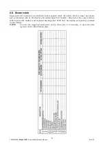
Summary of Contents for PURESTREAM MINI-CUBE QBS 001 EAA Option

Page 1: ...QBS Air Cooled Water Chiller User Manual MINI CUBE BY FRIULAIR PURESTREAM ...

Page 2: ...Editions Record Code Revision Edition Changes 7425MUM651 02 02 2018 Original instructions ITALIAN EN Translation of the original instructions ...

Page 3: ... of the chiller contains all essential information about the machine You will have to give this data to the manufacturer or reseller whenever you request information replacement parts etc during the warranty period Removing or tampering with the identification plate will void the warranty Warranty conditions For 12 months from the commissioning date and no more than 14 months from the shipping dat...

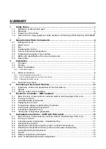
Page 4: ...ks and preparation for the first start up 12 4 2 Startup 12 4 3 Start up under critical conditions 12 5 Electronic Controller QBS standard 13 5 1 Main functions of the electronic controller buttons and meanings of the icons 13 5 2 Turning on and off 14 5 3 Controlling water temperature 14 5 4 Changing the set point 14 5 5 Temperature display as detected by the probes 14 5 6 Locking and unlocking t...

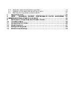
Page 5: ...the high pressure pressure switch 21 7 Operating Limits 22 8 SEPR SEASONAL ENERGY PERFORMANCE RATIO ACCORDING TO COMMISSION REGULATION EU 2016 2281 22 9 Maintenance Inspections And Periodic Checks 23 10 Troubleshooting 24 11 Dismantling The Chiller 26 12 Water Diagrams 27 13 Refrigerant Diagrams 28 14 Dimensional Drawings 29 ...

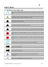
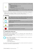
Page 6: ... instructions provided meticulously Risk of danger component or system under pressure Risk of danger component or system that can reach high temperatures during operation Risk of danger it is absolutely forbidden to use water to extinguish fires near or on the chiller Risk of danger it is absolutely forbidden to operate the machine with the panel open Service that can be performed by the machine s...

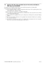
Page 7: ...The QBS chillers contain R134A refrigerant Operations on the cooling circuit must only be performed by specialist personnel with suitable equipment Any modifications to the machine or related operating parameters not previously verified and authorized by the Manufacturer may be hazardous and will invalidate the guarantee Do not use water to extinguish fires near or on the chiller 1 3 PROPER USE OF...

Page 8: ...he manufacturer s name data plate Do not solder on the exchangers or refrigerant fluid pipes Do not install the equipment in insufficiently ventilated rooms areas exposed to sources of heat or near inflammable substances During operation the equipment must not be subjected to vibrations that could cause fatigue failures Keep the documentation attached to the equipment user manual declaration of co...

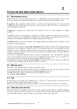
Page 9: ...igh pressure here thanks to a flow of forced air from the fans the high pressure refrigerant gas is cooled making it condensed and undercooled The flow of refrigerant liquid then passes through the lamination valve thermostatic expansion valve which drastically reduces its pressure the refrigerant liquid returns to the evaporator at a reduced pressure where it again evaporates taking heat from the...

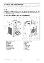
Page 10: ...TEGRITY OF THE MACHINE In addition to controlling the temperature the electronic controller uses pressure switches thermostats and timers to prevent and handle situations that could compromise the integrity of the machine also see Chapter 6 Safety Devices 2 7 QBS UNITS IDENTIFICATION OF THE MAIN COMPONENTS 04 High pressure switch 06 Compressor 08 Condenser 9 1 Fan 10 Refrigerant filter 11 Capillar...

Page 11: ... sticker each spare part is identified with its ID Number and related Spare Part Number Here below the cross reference table between ID Number and exploded drawings Ref With their description and quantity installed inside chillers NOTE To order the suggested spare parts or any other part it is necessary to quote the data reported on the identification plate ...

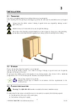
Page 12: ... stability before lifting 3 2 STORAGE Protect the machine from bad weather even if packed Always keep the chiller vertical even when in storage Turning it upside down can irreparably damage several parts of the unit If not used the chiller can be stored packed in an enclosed place free of dust with a maximum temperature of 50 C 122 F and specific humidity of not higher than 90 The packing material...

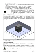
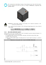
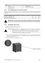
Page 13: ... winter anti freeze 3 3 1 Installation spaces To ensure the good functioning of the unit and access for maintenance you must respect the minimum installation space shown in the figure in this paragraph The exit of air from the fan must not be obstructed In any case avoid all situations in which hot air can circulate between the output of the fan and the intake of the machine Contact our office to ...

Page 14: ...he arriving and departing pipes be not less than the water fittings QBS 001 002 50 Hz 60 Hz Diameter of the in out water fittings 3 8 GAS FM 3 8 NPT FF 3 4 1 Recommended water system QBS 001 002 units come as standard with a tank at atmospheric pressure pump and bypass it is advisable to also provide the water circuit with A mechanical filter for water in the machine inlet pipes with mesh no great...

Page 15: ...ur company s sales offices to make sure that the mechanical seal and the pump motor are suitable for the type and concentration of fluid loaded in the hydraulic system 3 4 3 Charging the water circuit Check that the drain taps are turned off Open the system interception devices Attention Make sure that the tube that draws the inlet water to the pump is almost always fluid filled It is also recomme...

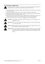
Page 16: ... a differential switch IDn 0 03A main power switch and slow blow fuses with the specifications shown on the electrical diagram Use wires of the section shown on the electrical diagram and in the following table Attention Never change the internal electrical connections as the warranty will be immediately voided Important Screw the wires solidly to the terminal strip of the cut off switch and lock ...

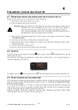
Page 17: ...h a tolerance of 10 Close the main power supply switch Close the cut off switch on the machine s electrical panel 4 2 STARTUP Connect the device power supply Touch the for 4 seconds The led will flash and turn off the chiller will switch on The controller will display the temperature of the water inside the tank if it is higher than the set value the compressor will start up To disable touch the f...

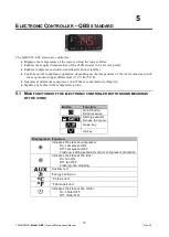
Page 18: ...tial 3 C 3K 5 4 F Guarantees minimum compressor on off times to maintain its integrity Signals any faults in the temperature probe 5 1 MAIN FUNCTIONS OF THE ELECTRONIC CONTROLLER BUTTONS AND MEANINGS OF THE ICONS Button Function On off button Exit procedure Setting setpoint Access the menu Down key Up key Display Led Function Indicates the state of compressor On compressor ON Off compressor OFF Fl...

Page 19: ...BS s electronic controller regulates the outlet water temperature on the basis of a set point value and an upper differential of 3 C 3K 5 4 F according to the following diagram 5 4 CHANGING THE SET POINT Touch the the flashing led indicates that the setpoint can be changed Use and keys within 15 seconds to change the temperature setpoint Touch key or do not operate for 15 seconds to confirm the va...

Page 20: ... keyboard is not locked and that no procedure is in progress Touch the key for 4 seconds the display will show the first label available Touch the or key to select the label rCH Touch the key Touch the or key within 15 seconds to set a password0F 1 Touch the key or do not operate for 15 seconds the display will show a flashing for 4 seconds after which the device will exit the procedure 5 8 SETTIN...

Page 21: ...ature probe 6 1 MAIN FUNCTIONS OF THE ELECTRONIC CONTROLLER BUTTONS AND MEANINGS OF THE ICONS Button Function Setting setpoint Down key Access the menu Up key Display Led Function Indicates the state of the fans On fan ON Off fan OFF Flashing fan stopping Celsius unit Fahrenheit unit Indicates the presence of alarms 6 2 TURNING ON AND OFF Connect the device power supply To turn on the instrument y...

Page 22: ...econds Press and 4 seconds and the display will show SP the first available parameter Press or to scroll the parameter list until you reach r0 To select the parameter press and use or in 15 seconds to modify the setting value Press to confirm the value or do not operate 15 seconds 6 5 SHOWING THE TEMPERATURE READ BY PROBE 1 AMBIENT TEMPERATURE Make sure the keyboard is not locked and no procedure ...

Page 23: ...iption Type of rearm AL1 Minimum temperature probe 1 ambient temperature Automatic AL2 Maximum temperature probe 2 outlet water temperature Automatic Pr1 Probe 1 error Automatic Pr2 Probe 2 error Automatic Loc Keyboard and or setpoint are locked The quantity to show is not available 6 9 SETTING CONFIGURATION PARAMETERS To gain access the procedure Press and 4 seconds and the display will show PA P...

Page 24: ...erature is activated AL1 4 C 39 2 F A4 Temperature the alarm of high temperature is activated AL2 50 C 122 F A10 Differential of parameter A1 At A1 A10 value the alarm AL1 will be deactiveted 2K A11 Differential of parameter A4 At A4 A11 value the alarm AL2 will be deactiveted 5K 6 11 ALTERNATIVE METHOD OF TEMPERATURE REGULATION The electronic controller allows to regulate the outlet working tempe...

Page 25: ...le Opt optional When they reach their calibration value most of the security devices trigger an alarm managed by the electronic controller For some safety devices once the cause of the alarm times out the machine resumes operation automatically as soon as the reset value is reached Others must be manually reset to restart the machine The following paragraph lists the characteristics of each safety...

Page 26: ... has fallen below the reset value see table Calibration of the safety devices and type of rearm in paragraph 6 1 High pressure switch For this reason when dealing with an intervention of the high pressure switch it is necessary to A Identify the cause of the rise in pressure fan not working condensation coil dirty or obstructed obstacles to the flow of exiting air operating temperature outside ope...

Page 27: ...us operation of the QBS units in relation to the temperature of the water exiting the machine and the temperature of the external air QBS 001 002 8 SEPR SEASONAL ENERGY PERFORMANCE RATIO ACCORDING TO COMMISSION REGULATION EU 2016 2281 Only for units at 50Hz power supply 230V 1Ph 50Hz Model QBS 001 002 SEPR 4 16 4 37 ...

Page 28: ...he pipes of the refrigerant circuit symptom of refrigerant leaks Every 6 months Check the tightness of the electrical terminals both inside the electrical panel and on the terminal strips of the compressors Yearly Check the contacts of the contactors if they show signs of deterioration replace them Yearly Check that the current absorbed by the machine is within the values on the identification pla...

Page 29: ...nnel Intervention of the main differential switch Electronic controller off Look for current leakage inside the machine Specialized personnel 2 The compressor does not start Intervention of the thermal protection inside the compressor The contactor of the compressor is on but the compressor is stopped Wait for cooling check that the compressor is working under normal conditions Check for insuffici...

Page 30: ...it create vacuum and recharge Specialized personnel Refrigerant filter clogged or thermostatic valve stuck Pipe downstream from the component covered with frost Check and replace Specialized personnel 5 Fan doesn t start Very low outside air temperatures and consequent intervention of the condensation control Fan icon off Condensation pressure normal The machine can working anyway 6 The unit is wo...

Page 31: ...or Copper Condenser Aluminium Carbon Steel Copper Pipes Copper Fan Aluminium Copper Steel Valves Steel Bronze Insulation Synthetic rubber without CFC EPS Polyurethane Pump Steel Copper Tank Stainless steel Electrical wires Copper PVC Electrical parts PVC Copper Bronze We recommend that you follow current safety norms for the disposal of each single material The refrigerant contains particles of lu...

Page 32: ...27 7425MUM651 Model QBS Use and Maintenance Manual Rev 02 12 WATER DIAGRAMS QBS 001 002 ...

Page 33: ...28 7425MUM651 Model QBS Use and Maintenance Manual Rev 02 13 REFRIGERANT DIAGRAMS QBS 001 002 14 ...

Page 34: ...29 7425MUM651 Model QBS Use and Maintenance Manual Rev 02 DIMENSIONAL DRAWINGS QBS 001 002 50Hz QBS 001 002 60Hz ...

Page 35: ...COOLING SOLUTIONS 3770B Laird Road Mississauga ON L5L 0A7 Tel 800 951 0777 905 820 3348 Fax 905 820 3490 www cagcooling com ...

Reviews: