2 Power connection and wiring
2.1 Core module and connection options
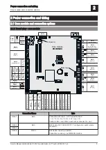
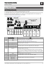
2.1.1 Board view - core module
6,3
A
T
sw +
gr -
IN
+24V
grün-gelb
rot +
blau -
ws 13VDC
NZ
COM
PZ
S
HE-
HE+
ZU
AUF
P2
5V/P3
ZU
AUF
P2
5V/P3
ws 13VDC
KM-35
(Betriebssignal)
KM-02
(Bus)
KM-01
(Bus)
KM-04
(COM 2)
KM-06
(Breitbandsonde)
KM-09
(Verriegelung)
(siehe T
abelle ...)
KM-10
(STB)
KM-11
(NOT-HALT)
KM-07
KM-07a
KM-08
KM-08a
KM-05
(COM 1)
KM-03
(Bus)
KM-36
(Optionsmodul)
L
N
PE
PE
PE
KM-34
(Heizkreispumpe 0
oder Brennerrelais)
KM-33
(Heizkreispumpe 1)
KM-32
(Heizkreispumpe 2)
KM-31
(Mischer 1)
KM-30
(Mischer 2)
KM-29
(Netz)
KM-28
(Pumpe 1)
KM-27
(Saugzug)
KM-15
(Abgasfühler)
KM-14
(Kesselfreigabe)
KM-13
(Lambdasonde)
FRKEM29
L1
N
N
L
N
L
N
L
N
LV
LV
L
Sig
+5V
N
L
N
AUF
ZU
N
AUF
ZU
+24V
Sig
+24V
KM-26
(PWM / 0-10V Pumpe 1)
KM-25
(Kesselfühler)
KM-24
(Rücklauf
fühler)
KM-23
(V
orlauf
fühler 1)
KM-22
(V
orlauf
fühler 2)
KM-21
(Raumfühler 1)
KM-20
(Raumfühler 2)
KM-19
(Außenfühler)
KM-18
(siehe T
abelle ...)
KM-17
(siehe T
abelle ...)
KM-16
(Türkontaktschalter)
KM-12
(Durchflussmesser)
Mains fuse
Core module
End jumper
Connection / Name
Note
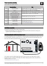
KM-01
BUS
Connection with cable – LIYCY paired 2x2x0.5;
⇨ See "Connecting the bus cable" [page 25]
Caution! CAN L and CAN H must not be connected to +U
BUS
!
KM-02
BUS
Patch cable CAT 5 RJ45 SFTP 1:1 configuration; pellet module
connection
KM-03
KM-04
COM 2
Null modem cable 9-pin SUB-D;
Connection is used e.g. as MODBUS interface
Power connection and wiring
2
Core module and connection options
Service Manual Lambdatronic P 3200 for pellet boiler (4,3" Touch) | B1620121_en
5
Summary of Contents for Lambdatronic P 3200
Page 85: ...6 Notes Notes 6 Service Manual Lambdatronic P 3200 for pellet boiler 4 3 Touch B1620121_en 85...
Page 86: ...6 Notes 86 Froling GesmbH A 4710 Grieskirchen Industriestra e 12 www froeling com...
Page 87: ...Notes 6 Service Manual Lambdatronic P 3200 for pellet boiler 4 3 Touch B1620121_en 87...


