background image

2.3.1 Connecting the bus cable

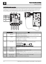
For the bus connections between the individual modules cable type LIYCY paired 2x2x0.5 should be used. The
connection to the 5-pin plugs should be carried out according to the following diagram:

+U

BUS

CAN H

CAN L

+U

BUS

CAN H

CAN L

Braided shield

White

Green

Yellow
Brown

Braided shield

White

Green
Yellow
Brown

2.3.2 Setting end jumpers

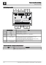
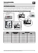
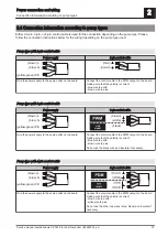
NOTICE! To ensure smooth running of the bus system, the jumper must be set on the first and last module.
When using a bus repeater, the two galvanically separated sub-networks must be considered separately. The
jumpers for each network must be set on the first and last module.

End jumper not set

End jumper set

If the contacts at the base of the end jumper are not bridged (image left), it is referred to as “not set". In this
case there is no bus termination. If the contacts are closed (image right), the end jumper is set and the bus
connection is terminated.


2

Power connection and wiring

BUS connection

30

Froling GesmbH | A-4710 Grieskirchen, Industriestraße 12 | www.froeling.com

Summary of Contents for Lambdatronic SP 3200

Page 1: ...n 60 01 Build 01 36 Translation of the original German installation instructions for technicians Read and follow the instructions and safety information Technical changes typographical errors and omissions reserved B1460720_en Edition 30 04 2020 Froling GesmbH A 4710 Grieskirchen Industriestraße 12 www froeling com ...

Page 2: ...ith settings wizards 34 3 1 Before switching on for the first time 34 3 1 1 Controller check 34 3 1 2 Check on the connected units 34 3 1 3 System check 34 3 2 General information about the settings wizard 35 3 3 Switching on for the first time 37 3 4 Starting the setting wizard 38 4 Parameters overview 39 4 1 Heating 39 4 1 1 Heating Status 39 4 1 2 Heating Temperatures 40 4 1 3 Heating Times 41 ...

Page 3: ...eration hours 102 4 15 3 System Sensors and pumps 102 4 15 4 System System selection 102 4 16 Diagnostics 103 4 16 1 Diagnosis Current fault list 103 4 16 2 Diagnosis Clear pending error 103 4 16 3 Diagnostics Error history 103 4 16 4 Diagnostics Clear error history 103 4 17 Touchscreen 105 4 17 1 Touchscreen Display settings 105 Display settings General 105 Display settings Basic display 106 Disp...

Page 4: ...ried out on electrical components Always have work carried out by a qualified electrician Observe the applicable standards and regulations Work must not be carried out on electrical components by unauthorised persons WARNING When touching hot surfaces Severe burns are possible on hot surfaces and the flue gas pipe When work is carried out on the boiler Shut down the boiler according to procedure O...

Page 5: ... N AUF ZU N AUF ZU KM 26 PWM 0 10V Pumpe 1 KM 25 Kesselfühler KM 24 Rücklauffühler KM 23 Vorlauffühler 1 KM 22 Vorlauffühler 2 KM 21 Raumfühler 1 KM 20 Raumfühler 2 KM 19 Außenfühler KM 18 Fühler 1 KM 17 Fühler 2 KM 16 Türkontaktschalter KM 15 Abgasfühler KM 14 Kesselfreigabe KM 13 Lambdasonde KM 12 Durchflussmesser End jumper Mains fuse Core module Connection Name Note KM 01 BUS Connection with c...

Page 6: ... Boiler release Connection cable1 2 x 0 75 mm2 Caution The connection must be a floating connection See Boiler enable contact page 9 KM 15 Flue gas temperature sensor Only use connection cable of the component KM 16 Door switch Connection cable1 2 x 0 75 mm2 KM 17 Sensor 2 Connection cable1 2 x 0 75 mm2 KM 18 Sensor 1 Connection cable1 2 x 0 75 mm2 sensor 1 in the STL housing KM 19 Outside tempera...

Page 7: ... for the wiring this must be of the correct size to comply with applicable regional standards and regulations Boiler type Electric fuses Fuse type S1 Turbo 16A C16A S1 Turbo F 16A C16A S3 Turbo 13A C13A S4 Turbo 16A C16A S4 Turbo F 16A C16A 2 1 3 Connecting the outside temperature sensor The outside temperature sensor is included with the materials supplied for the boiler and is usually mounted on...

Page 8: ...mperature sensor connection Alternatively the outside temperature sensor can be connected to an additional heating circuit module See Heating circuit module page 14 2 Power connection and wiring Core module and connection options 8 Froling GesmbH A 4710 Grieskirchen Industriestraße 12 www froeling com ...

Page 9: ...6 3 AT sw gr IN 24V grün gelb rot blau ws 13VDC NZ COM PZ S HE HE ZU AUF P2 5V P3 ZU AUF P2 5V P3 ws 13VDC KM 35 Betriebssignal KM 02 Bus 04 M 2 06 ndsonde 09 gelung 10 TB M 11 HALT 07 abelle 08 abelle 05 M 1 KM 03 Bus KM 36 Optionsmodul L N PE PE PE KM 34 Heizkreispumpe 0 oder Brennerrelais KM 33 Heizkreispumpe 1 KM 32 Heizkreispumpe 2 KM 31 Mischer 1 KM 30 Mischer 2 KM 29 Netz KM 28 Pumpe 1 KM 2...

Page 10: ... N PE L LV N Netz PE L AO P1 PWM 0 10V Connect the power supply for the high efficiency pump to output Pump 1 of the core module Connect the PWM cable of the high efficiency pump to the corresponding PWM 0 10V port Make sure that the cables are configured correctly polarity in accordance with the connection diagram of the pump Set control of the pump in the relevant menu to Field pump PWM or Field...

Page 11: ...l signal AC pump without control signal pulse package control On older pumps without a control signal that are not highly efficient the speed control is implemented via a pulse package control Please note that the minimum speed may need to be adjusted on some pumps default setting 30 FRKEM29 Pumpe 1 N PE L LV N Netz PE L AO P1 Connect pump to output Pump 1 of the core module In the relevant menu s...

Page 12: ...etz PE L AO P1 HKP0 N PE L1 Phase L for switching the valve and connecting neutral conductor N to output Pump 1 with the RC element Phase L for continuous supply switches the valve back to the initial position at output HCP0 connect terminal L1 2 Power connection and wiring Core module and connection options 12 Froling GesmbH A 4710 Grieskirchen Industriestraße 12 www froeling com ...

Page 13: ...to switch the phase At above 5 Ampere the pump must be isolated with a relay HKP 0 N PE L1 Wire the floating output contact as an enabling signal to control the standby boiler 2 1 9 Operating signal On the core module connection position KM 35 it is possible to issue a floating operating signal The status is displayed under the Standby relay output in the Manual Digital outputs menu See Manual Dig...

Page 14: ...the bus cable page 30 Caution CAN L and CAN H must not be connected to UBUS HE 02 BUS HE 03 Flow temperature sensor 1 Connection cable1 2 x 0 75 mm2 HE 04 Flow temperature sensor 2 HE 05 Room temperature sensor 1 Connection cable1 2 x 0 75 mm2 shielded from 25 m cable length HE 06 Room temperature sensor 2 HE 07 Sensor 1 Connection cable1 2 x 0 75 mm2 Connection of the outside temperature sensor i...

Page 15: ...02 BUS Connection with cable LIYCY paired 2x2x0 5 See Connecting the bus cable page 30 Caution CAN L and CAN H must not be connected to UBUS HY 04 BUS HY 05 AO P1 Connection cable1 2 x 0 75 mm2 Connection of the control signal PWM or 0 10V of the relevant pump AO P1 pump 1 of the board HY 06 AO P2 HY 07 HY 12 Sensor _ 1 Sensor _ 6 Connection cable1 2 x 0 75 mm2 shielded from 25 m cable length Sens...

Page 16: ...07 HY 12 Sensor _ 1 Sensor _ 6 Connection cable1 2 x 0 75 mm2 shielded from 25 m cable length Sensor inputs on the board The correct sensor designation is determined by the set module address 0 7 Example Module address 2 sensor 2 1 to sensor 2 6 HY 13 Mains Connection cable1 3 x 1 5 mm2 fuse 10A HY 14 Pump _ 1 Connection cable1 3 x 1 5 mm2 max 1 5A 230V 280W Pump outputs on board The correct pump ...

Page 17: ...FRHYU21 N Pumpe 1 Netz PE L N PE L AO P1 PWM 0 10V FRHYU22 PWM 0 10V N AO P1 Pumpe 1 Netz PE L N PE L L Hydraulic module FRHYU21 Connect the power supply for the high efficiency pump to Pump 1 or Pump 2 output Hydraulic module FRHYU22 Connect the power supply for the high efficiency pump to output Pump 1 or Pump 2 and use the relay output for phase L Connect the PWM cable of the high efficiency pu...

Page 18: ... control signal AC pump without control signal pulse package control On older pumps without a control signal that are not highly efficient the speed control is implemented via a pulse package control Please note that the minimum speed may need to be adjusted on some pumps default setting 30 up to hydraulic module Version FRHYU21 up to hydraulic module Version FRHYU22 FRHYU21 N Pumpe 1 Netz PE L N ...

Page 19: ...rsion FRHYU22 FRHYU22 N AO P1 Pumpe 1 Netz PE L N PE L L L N L N PE 22 12 24 14 21 11 A2 A1 230 VAC power supply Hydraulic module FRHYU22 Connect the pump relay to output Pump 1 or Pump 2 and use the relay output for phase L Install and connect two pole cable 2 x 0 75 mm2 from connection AO P1 or AO P2 to the pump and connect terminal with terminal IN of the pump Install and connect two pole cable...

Page 20: ... Pumpe 1 Netz PE L N PE L L Hydraulic module FRHYU21 Phase L for switching the valve and connecting neutral conductor N to output Pump 1 or Pump 2 with the RC element Hydraulic module FRHYU22 Phase L for switching the valve and connecting neutral conductor N to output Pump 1 or Pump 2 using the relay output for phase L Connect the phase L for continuous supply switches the valve back to the initia...

Page 21: ...L 01 Rücklaufmischer RL 02 Netz RL 03 Netz RL 04 Bus RL 05 Bus FRRLA10 Return mixer module Connection Name Note RL 01 Return mixer Connection cable1 4 x 0 75 mm2 max 0 15A 230V RL 02 Mains Connection cable1 3 x 1 5 mm RL 03 Mains RL 04 Bus Patch cable CAT 5 RJ45 SFTP 1 1 configuration included in delivery RL 05 Bus 1 YMM as per ÖVE K41 5 or H05VV F as per DIN VDE 0881 5 Connection example Power co...

Page 22: ...16 Bus PM 10 Rückbrandklappe PM 11 Rostantrieb PM 21 Pelletmodulerweiterung L_STB L L N FRPEM25 Pellet module End jumper Fuses Connection Name Note PM 01 Ignition Use connection cable of the component PM 02 WOS drive PM 03 Ash screw PM 04 Ash screw PM 05 Mains connection Connection cable1 3 x 1 5 mm2 PM 06 Pellets suction turbine Connection cable1 3 x 1 5 mm2 PM 07 Stoker motor Use connection cabl...

Page 23: ...ing devices signal lights signal horn SMS box etc If a fault occurs both contacts are activated and the normally open closes and the normally closed opens Maximum load of the contact 1A N L N L N L N L N L N L N L N IN 24V OFFEN 24V GESCHL 24V GND OUT OFFEN GESCHL AUF ZU GND 24V L PM 01 Zündung PM 02 siehe Tabelle PM 03 Ascheschnecke PM 04 Ascheschnecke PM 05 Netz F1 F2 PM 06 Saugturbine PM 07 Sto...

Page 24: ...ing boiler heat exchanger PE 02 Digi IN Connection cable1 2 x 0 75 mm2 24VDC Digital input 24V that determines the position of the room air flap Digital input 1 Flap open Digital input 0 Flap closed PE 03 Jam sensor Jam sensor in suction piece on vacuum screw delivery system Connection layout Jam sensor S2 GND IN 24V blue black brown NO IMPORTANT The white wire of the sensor is not used PE 04 Rese...

Page 25: ...PE A1 A2 Mains Pellet mole RC element Discharge screw 8 Using the RC element provided connect terminals A1 and A2 of the relay base to ports L and N on the discharge screw output of the pellet module expansion as illustrated Connect L and N of the power supply line for the pellet mole to the COM terminals of the relay switch contacts and wire from the NO terminals to the pellet mole Power connecti...

Page 26: ... 04 Bus AN 05 Power supply 24 V power supply of the module connection cable1 2 x 1 0 mm Firewood boiler Supply via 24 V power supply unit Pellet boiler and dual fuel boiler Pellet module MIN sensor terminal Wood chip boiler Supply via 24 V power supply unit AN 06 Thermocouple Use sensor connection 1 YMM as per ÖVE K41 5 or H05VV F as per DIN VDE 0881 5 Standard configuration Analogue module with a...

Page 27: ...itiate start up via the power demand Automatic mode must be selected and the contact must be closed if a release contact is used Boiler release input available parameter YES Necessary parameters for the parameterisation of the power demand are in the menu Boiler General settings 2 2 7 Digital module FRDGM13 DG 05 Bus DG 04 Bus 8 7 6 5 4 3 2 1 DG 01 Ausgänge DG 02 Versorgung DG 03 Eingänge 8 7 6 5 ...

Page 28: ...compact 1 2 3 suction module PL OPEN terminal 2 1 2 3 suction module PL CLOSED terminal 3 1 2 3 suction module SL OPEN terminal 4 1 2 3 suction module SL CLOSED terminal 2 Power connection and wiring Expansion modules 28 Froling GesmbH A 4710 Grieskirchen Industriestraße 12 www froeling com ...

Page 29: ...hough no specific sequence of the module types and addresses is specified A star stub cable is not permitted As the control units are supplied with voltage in addition to transferring data problems caused by voltage drops can occur depending on the number of modules and existing cable lengths A voltage supply unit must be used for every touch room console heating circuit module hydraulic module Po...

Page 30: ...the jumper must be set on the first and last module When using a bus repeater the two galvanically separated sub networks must be considered separately The jumpers for each network must be set on the first and last module End jumper not set End jumper set If the contacts at the base of the end jumper are not bridged image left it is referred to as not set In this case there is no bus termination I...

Page 31: ...dule addresses address 1 7 are set Important Only set the module address when the device is disconnected from the power supply Module address set Heating circuit module Hydraulic module Heating circuit Sensors Pump 0 03 04 0 1 0 6 0 1 0 2 1 05 06 1 1 1 6 1 1 1 2 2 07 08 2 1 2 6 2 1 2 2 3 09 10 3 1 3 6 3 1 3 2 4 11 12 4 1 4 6 4 1 4 2 5 13 14 5 1 5 6 5 1 5 2 6 15 16 6 1 6 6 6 1 6 2 7 17 18 7 1 7 6 7...

Page 32: ...tion line NOTICE The dimensions of the equalization line must be installed by a specialist in accordance with regional regulations Instead of the potential equalisation a Fröling bus repeater can be used in the bus connection line to the next building The potential separation galvanic isolation allows the bus network to be split into two separate sub networks A B C D E F G H I J A B C D E F G H I ...

Page 33: ...own L blue N yellow green PE not used brown white black Wire the power supply to the pump outlet on the board Connect the control cable to the PWM output on the board making sure that the polarity is correct blue wire to earth brown wire to plus Do not use the black wire and insulate if necessary Pump type with 4 pin control cable Power supply 4 pin control cable brown L blue N yellow green PE Wir...

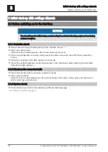
Page 34: ...onnection of the BUS cable for short circuits Check the specified addresses and terminal jumpers on the individual modules heating circuit modules hydraulic modules displays 3 1 2 Check on the connected units Check that all units that are used are connected correctly Carry out wiring check Check for loose or uninsulated wires in the terminal boxes of the pumps mixing valve and switch valve which c...

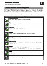
Page 35: ... boiler specific options ignition filter etc Lambda probe Selection and calibration of the type of sensor used Feed system Selection of the existing discharge system only for boilers with automatic loading Hydraulic system Selection of the hydraulic system hydraulic system 1 2 3 etc Additional components Selection and activation of the existing load and control components heating circuits DHW tank...

Page 36: ...ng the control signal of the respective pump The following options are available depending on the selected menu Pump without control line HE pump without control line Field pump PWM Solar pump PWM Field pump PWM valve Solar pump PWM valve Field pump 0 10 V Solar pump 0 10 V Field pump 0 10 V valve Solar pump 0 10 V valve Isolating valve See PDM 0 10V settings page 109 7 Continue to the next step 8...

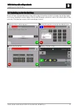
Page 37: ...ge production number of the boiler system date and time Then the basic screen of the touch display is shown 1 Selection of the controller language 2 Setting the production number see identification plate 3 Setting the date and time 4 Display of the basic screen Initial start up with settings wizards 3 Switching on for the first time Service manual Lambdatronic SP 3200 for dual fuel boiler B1460720...

Page 38: ...onfirm 3 Tap the icon of the settings wizard 4 Tap the Boiler setting wizard 5 The settings wizard loads 6 Read the information text and continue with YES to start 3 Initial start up with settings wizards Starting the setting wizard 38 Froling GesmbH A 4710 Grieskirchen Industriestraße 12 www froeling com ...

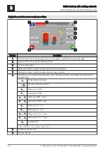
Page 39: ...l another mode is activated Party Party mode the current or next setback phase is ignored OFF Switched off heating circuit deactivated only frost protection Actual flow temperature Display of the current flow temperature Flow temperature setpoint Display of the calculated flow temperature setpoint Room temperature Prerequisite Heating circuit used in conjunction with remote control Display of the ...

Page 40: ...e at which heating circuit pump switches off in heating mode If the outside air temperature exceeds this value during heating the heating circuit pumps and mixing valve are deactivated External temperature at which heating circuit pump switches off in setback mode If the outside air temperature falls below this value in setback mode the heating circuit pumps and mixing valve are activated Maximum ...

Page 41: ...ing DHW tank loading From which buffer tank or distributor is the heating circuit supplied 0 boiler Prerequisite Parameter can only be used in conjunction with multiple house systems variants This parameter defines the allocation of the heat source for this heating circuit 0 boiler 1 buffer tank 01 High temperature requirement because of DHW tank 1 loading NO The heating circuit is operated accord...

Page 42: ...er buffer tank loading times are automatically set to 0 00 24 00 and the outside air temperature heating limit is ignored When using a firewood boiler a corresponding heat supply must be ensured If the actual flow temperature setpoint required cannot be reached or maintained e g boiler output then no warning is displayed In the event of a power failure the program continues from the point at which...

Page 43: ... 40 45 50 55 60 1 6 11 16 21 26 Day Flow temp setpoint C 30 Heating up program 7 0 5 10 15 20 25 30 35 40 1 6 11 16 21 26 Day Flow temp setpoint C 30 The heating up programs listed are non binding recommendations If the heating up program is to be used for floor screed drying you must consult the manufacturer of the floor finish and or the installer Configure program 8 Heating up program Service C...

Page 44: ...sor is connected 0 core module If the outside temperature sensor is not connected to the core module the address of the relevant heating circuit module 1 must be set here Sensor 1 on relevant module Use room sensor input for room thermostat NOTICE This parameter influences all sensor connections which an analogue room temperature sensor can be connected to NO At the sensor connector of the room se...

Page 45: ...ue set here the time window is active and the loading source boiler or buffer tank indicates the set loading increase and the DHW tank loading is started Load if temperature difference between buffer tank and DHW tank is When the buffer tank top temperature is above the current DHW tank temperature by this value and the time window is active the DHW tank loading is started Only for systems with bu...

Page 46: ...heating be carried out Determines the day of the week on which the Legionella heating of the domestic hot water is carried out DHW tank temp setpoint for legionella heating same for all DHW tanks If the parameter Legionella heating activated is set to YES the DHW tank is heated to the set temperature on the specified day of the week Which buffer tank or heat distributor supplies the heat to this D...

Page 47: ...ding to pump manufacturer s instructions Maximum DHW tank pump speed If you need to limit the maximum speed of the boiler loading pump for systemic reasons you can do so by adjusting this parameter Parameters overview 4 Water Service manual Lambdatronic SP 3200 for dual fuel boiler B1460720_en 47 ...

Page 48: ...that has been supplied by the solar panel system today Daily yield 1 day ago kWh Daily yield 2 days ago kWh Daily yield 3 days ago kWh Daily yield 4 days ago kWh Daily yield 5 days ago kWh Daily yield 6 days ago kWh Shows the historical progression of the solar panel system The yields of the last 6 days are available Daily yield 2 days ago kWh Daily yield 3 days ago kWh Daily yield 4 days ago kWh ...

Page 49: ...Minimum temperature at collector which must be reached in order for the solar control to start Collector pump protection from a collector temp If the measured value of the solar collector sensor exceeds the set value then the solar collector must cool down by 20 C within 15 minutes otherwise the solar collector pump stops in order to protect the pump Heat exchanger buffer tank pump start delay Pre...

Page 50: ...ollector pump speed Adjustment of the minimum speed to the pump type Set the pump mode according to pump manufacturer s instructions Maximum collector pump speed If you need to limit the maximum speed of the collector pump for systemic reasons you can do so by adjusting this parameter Collector monitoring YES The collector pump is switched on at regular intervals for 10 seconds The time can be def...

Page 51: ...t exchanger and buffer tank is connected Control of storage tank heat exchanger pump Prerequisite Hydraulic system 12 or 13 Definition of control signal for pump type used See PDM 0 10V settings page 109 Pump outlet of DHW tank heat exchanger pump Prerequisite Hydraulic system 12 Pump outlet to which the pump between the solar heat exchanger and DHW tank is connected Control of DHW tank heat excha...

Page 52: ...site External volume pulse transmitter installed Display of the water quantity currently being pumped through the solar collector Todays yield kWh Display of the heat quantity that has been supplied by the solar panel system today Daily yield 1 day ago kWh Daily yield 2 days ago kWh Daily yield 3 days ago kWh Daily yield 4 days ago kWh Daily yield 5 days ago kWh Daily yield 6 days ago kWh Shows th...

Page 53: ...ut to which the sensor for the heat meter flow temperature is connected Is an external flow through counter used YES An external volume pulse transmitter is in use Parameters overview 4 Solar Service manual Lambdatronic SP 3200 for dual fuel boiler B1460720_en 53 ...

Page 54: ...on Display of the current temperature in the lower part of the buffer tank Buffer tank middle temperature Prerequisite Middle buffer tank temperature sensor installed Display of the current temperature in the mid area of the buffer tank Buffer tank bottom temperature Display of the current temperature in the lower part of the buffer tank Buffer tank pump control Display of the current speed of the...

Page 55: ...e or hydraulic system 4 If the buffer tank charge is greater than the specified value the boiler system follows the shutdown procedure Buffer tank fully loaded if temperature difference between boiler and bottom buffer tank From this difference between the boiler temperature setpoint that has been set and the current temperature in the lower part of the buffer tank buffer tank loading is stopped B...

Page 56: ... of the buffer tank is used as the loading criterion Control buffer tank requests according to system environment NO The start criterion of the boiler is defined via the parameter Boiler start if difference between boiler setpoint and top buffer is larger YES All heating circuits and DHW tanks that are connected to the boiler system and activated report requirements back to the controller on the b...

Page 57: ... is used for calculating the required amount of fuel for loading the storage tank If the boiler is active then charge all buffer tanks Prerequisite Variant 3 or variant 4 YES Starting the boiler due to a heating requirement by the storage tank in the boiler system not only loads this storage tank but all of the storage tanks in sub stations This increases the runtime related to a boiler system sta...

Page 58: ...current position of the primary air flap Adjusted for the air settings Residual oxygen content Display of the current residual oxygen content Oxygen control Secondary air Display of the current value of the secondary air flap according to controller Position of secondary air flap Display of the current position of the secondary air flap Adjusted for the air settings Air speed at suction opening Di...

Page 59: ...t 2 and 5 or Variant 3 Return mixer is controlled only when the store loading pump is active If the pump stops the mixer closes the total return opens the bypass Temperature in the hi limit stat housing at which all pumps run When the current temperature on the safety temperature limiter reaches this value the buffer loading pump is activated and also the heating circuit pumps and boiler loading p...

Page 60: ...es to the parameter Minimum boiler temperature to release all pumps YES The HKP0 output closes when the boiler switches to Off status Control boiler loading pump using pump 1 Prerequisite Variant 4 NO Connection of boiler loading pump at output HKP0 on core module YES Connection of boiler loading pump at output Pump 1 on core module Control of boiler loading pump Prerequisite Variant 4 Definition ...

Page 61: ... on the display Reset the remaining heating hours until ash removal warning NO The service hours counter until ash removal warning continues to run YES The service hours counter is set to the value in menu Pellet feed under parameter Heating hours until ash removal warning Modem installed NO The boiler does not have a modem for data transfer installed YES The boiler has a modem for data transfer i...

Page 62: ...ule input for external power demand Boiler General settings MODBUS settings System menu Boiler MODBUS settings COM 2 is used as a MODBUS interface NO The COM 2 interface sends the most important boiler values every second YES The COM 2 interface can be used to connect a MODBUS RTU ASCII MODBUS address Defines the address of the boiler in the Modbus network MODBUS protocol 1 RTU 2 ASCII Indicates w...

Page 63: ...here Customer number By setting the customer number this is automatically transferred into the commissioning report when it is saved Boiler number By setting the boiler number this is automatically transferred into the commissioning report when it is saved Parameters overview 4 Boiler Service manual Lambdatronic SP 3200 for dual fuel boiler B1460720_en 63 ...

Page 64: ...t to NO Display of the current pump control for the secondary boiler Secondary boiler switching valve Prerequisite Isolating valve installed parameter set to YES Display of the current isolating valve control of the secondary boiler Manual start of secondary boiler only when ID fan is switched off OFF Secondary boiler is controlled according to the program that is set ON Secondary boiler is activa...

Page 65: ...nce the set duration has elapsed Start standby boiler only after storage tank top Standby boiler enabled after temperature decreases below minimum temperature on top storage tank No consumers are taken into consideration Secondary boiler minimum runtime If the secondary boiler is started it will run for at least the length of time set here Minimum temperature of secondary boiler When the secondary...

Page 66: ...ry boiler or the secondary boiler switch valve is connected Control of boiler 2 pump Definition of control signal for pump type used See PDM 0 10V settings page 109 Maximum speed of boiler 2 pump If you need to limit the maximum speed of the loading pump of the secondary boiler for systemic reasons you can do so by adjusting this parameter Invert secondary boiler isolating valve YES If the valve s...

Page 67: ...specified values for the chosen fuel selection should be adopted Fuel selection Wet firewood If firewood is to be burnt with a water content w of more than 15 then this setting must be selected A prompt message then appears to confirm whether the specified values for the chosen fuel selection should be adopted Parameters overview 4 Fuel Service manual Lambdatronic SP 3200 for dual fuel boiler B146...

Page 68: ...an be called up 2 Selected suction point should be started by the selection unit probes The area of the suction point flashes alternately grey green until the desired position is reached 3 Selected suction point is available 4 If the selected suction point is generally not in use or should not be used due to a problem suction hose blockage by pellets etc the suction point can be locked by tapping ...

Page 69: ...obes The area of the suction point flashes alternately grey green until the desired position is reached 3 Selected suction point is available 4 If the selected suction point is generally not in use or should not be used due to a problem suction hose blockage by pellets etc the suction point can be locked by tapping on this area 5 6 If a combination of several RS4 RS8 pellet discharge systems is be...

Page 70: ...t NOTICE This parameter is not in use for feed system 3 probe switch Suction run on When the fill level sensor detects fuel in the cyclone the suction turbine remains active for the time set Refill cyclone after buffer charging NO A filling process of the pellet container is carried out according to the filling times that are set YES If the boiler shuts down once buffer tank loading is complete th...

Page 71: ...splay of the total calculated pellet consumption Upon start up or after a software update to at least software version 50 04 Build 05 09 the counter is automatically activated Start the process for determining the pellet feed rate Used to determine the amount of pellets conveyed for the calculation of pellet consumption Before starting place a suitable container in the combustion chamber to collec...

Page 72: ...the instructions for heating up with the automatic ignition Date and time method Ignition starts at the specified time exactly If the parameter is set to daily instead of the date ignition starts every day at the specified time Buffer tank min method The ignition process starts if heat is requested from the buffer tank from the specified time parameter Boiler start if difference between boiler set...

Page 73: ...utor 2 Speed distributor 2 pump Prerequisite Variant 2 or variant 3 and pump for distributor 2 installed Display of the current speed of distributor 2 pump Return temperature distributor 3 Prerequisite Variant 2 or variant 3 and pump for distributor 3 installed Display of the current return temperature from distributor 3 Speed feeder 3 Prerequisite Variant 2 or variant 3 and pump for distributor 3...

Page 74: ...e from distributor 2 is regulated to the value set here When the return temperature from distributor 2 reaches the specified value the pump for distributor 2 starts up at minimum speed Return temperature setpoint distributor 3 Prerequisite Variant 2 or variant 3 and pump for distributor 3 installed The return temperature from distributor 3 is regulated to the value set here When the return tempera...

Page 75: ...et to which the pump for distributor 1 is connected Control of distributor 1 pump Prerequisite Variant 1 and pump for distributor 1 installed Definition of control signal for pump type used See PDM 0 10V settings page 109 Minimum speed for distributor 1 pump Prerequisite Variant 1 and pump for distributor 1 installed Adjustment of the minimum speed to the pump type Set the pump mode according to p...

Page 76: ...nd pump for distributor 3 installed If you need to limit the maximum speed of the distributor 3 pump for systemic reasons you can do so by adjusting this parameter Sensor input of distributor 4 return sensor Prerequisite Variant 2 or variant 3 and pump for distributor 4 installed Sensor input to which the sensor for the return distributor 4 is connected Pump output of distributor 4 pump Prerequisi...

Page 77: ...of the backup boiler Slave boiler OK Display of whether the backup boiler is ready for operation Slave boiler is heating Display of whether the backup boiler is in Heating operating status Slave boiler control variable Display of the signal for the combustion controller Boiler charging pump speed Display of the current speed of the boiler loading pump Parameters overview 4 Cascade Service manual L...

Page 78: ...pecified value This parameter defines the base point of the charging curve of the buffer tank Start point 1 at buffer tank charge If the buffer tank charge is lower than this value the first boiler is started This can be the boiler with the highest priority or with the fewest operating hours and consequently both the master and the slave boiler Start point 2 at buffer tank charge If the buffer tan...

Page 79: ...y the order in which the boilers start Where boilers have the same priority the boiler currently with the fewest operating hours always starts first With this setting the master boiler always starts first as it has the highest priority the boilers then start in numerical order Start priority of the master boiler 1 Start priority of slave boiler 1 2 Start priority of slave boiler 2 3 Start priority...

Page 80: ...nce Temperature difference between heat source and heat sink which must be reached to activate the pump of the differential controller Shutdown difference If the temperature difference between the heat source and the heat sink falls below this value the pump of the differential controller is deactivated Minimum temperature for heat source If the temperature in the heat source falls below this valu...

Page 81: ...manufacturer s instructions Maximum pump speed If you need to limit the maximum speed of the pump of the differential controller for systemic reasons you can do so by adjusting this parameter Sensor input of heat source sensor Sensor input to which the heat source sensor is connected Sensor input of heat sink sensor Sensor input to which the heat sink sensor is connected Sensor monitoring YES If t...

Page 82: ...on pump is also activated at a signal from the flow valve YES The circulation pump is controlled according to time program and temperature at the return circulation line In conjunction with the use of a flow switch the circulation pump is also activated at a signal from the flow switch NOTICE Connect the flow sensor as the return sensor Switch off the pump at what return temperature in the circula...

Page 83: ...put to which the flow switch is connected Pump output of circulation pump Pump outlet to which the circulation pump is connected Control of circulation pump Definition of control signal for pump type used See PDM 0 10V settings page 109 Maximum speed of the circulation pump If you need to limit the maximum speed of the circulation pump for systemic reasons you can do so by adjusting this parameter...

Page 84: ...ellet the WOS is activated via a combined drive with the ash screw Ignition ON The hot air blower ignition rod for igniting the fuel is activated Back burn flap drive ON Burn back flap is opened Manual filling of pellet container only starts when gate valve is open ON The gate valve of the pellet container opens the container is then filled with pellets until the switch point of the level sensor i...

Page 85: ...ating Circuit 1 Mixer OPEN Standby relay Ignition 4 14 3 Manual Analogue outputs System menu Manual Analogue outputs The parameters displayed depend on the boiler configuration A 0 Automatic Off A 1 100 Automatic with value ON 1 100 Manual with value ON 0 Manual Off Primary air Pump 0 1 Parameters overview 4 Manual Service manual Lambdatronic SP 3200 for dual fuel boiler B1460720_en 85 ...

Page 86: ...rs displayed depend on the boiler configuration A 0 Automatic Off A 1 Automatic On 1 Manual On 0 Manual Off Cyclone 1 max sensor Door switch Hi limit stat input E stop input 4 Parameters overview Manual 86 Froling GesmbH A 4710 Grieskirchen Industriestraße 12 www froeling com ...

Page 87: ...urn mixer only with active storage tank pump Prerequisite Variant 2 and 5 or Variant 3 Return mixer is controlled only when the store loading pump is active If the pump stops the mixer closes the total return opens the bypass Temperature in the hi limit stat housing at which all pumps run When the current temperature on the safety temperature limiter reaches this value the buffer loading pump is a...

Page 88: ...emperature must at least exceed the value set here Flue gas Flue gas difference for start process When the boiler controller changes to Pre heating status the current value of the flue gas temperature is stored When the flue gas temperature rises by the specified value set here during Pre heating or Ignition status the boiler controller switches to Heating status Safety time If the condition Minim...

Page 89: ...ied time 75 spray valve active for 15 sec and 5 sec pause Reduce pump release temp in heat up phase by In firewood boilers with a calorific value heat exchanger the store loading pump is enabled in the heat up phase at a lower temperature to achieve an earlier flow through the heat exchanger Difference between return setpoint and boiler temp in heat up phase During the heat up phase the desired re...

Page 90: ...stem environment e g heating circuit is compared with the current buffer tank temperature from the specified time If the top buffer tank temperature falls below the maximum flow temperature setpoint the ignition process starts The Ignition time date time period applies from the specified time until 24 00 h on the specified date If the specified time is not subsequently changed and ignition is not ...

Page 91: ... the secondary air flap does not change within this set period of time a warning appears on the display ID fan during heating up In Heating up status the induced draught blower fan is operated with the specified control ID fan during pre heating In Pre heating status the induced draught blower fan is operated with the specified control ID fan during shutdown In Shutdown status the induced draught ...

Page 92: ...ot active Duration of LW Heat Shut down If firewood is ignited via the pellet unit then the pellet unit starts the cleaning process of the pellet unit at the end of the specified time WOS start time Time from which the heat exchanger cleaning system can be activated WOS stop time Time to which the heat exchanger cleaning system can be activated Heating hours until ash removal warning Once the spec...

Page 93: ...changer cleaning system will be activated after the set time has elapsed for the duration set under the WOS runtime parameter If the boiler switches to Slumber mode the heat exchanger cleaning system will be activated after a third of the time set here has elapsed for the duration set under the WOS runtime parameter Function in pellet mode If the boiler shuts down because of a pellet suction reque...

Page 94: ...set Max runtime of suction fan Prerequisite Vacuum screw filling system installed or vacuum screw filling system automatically operated installed If the 100 fill level has not been reached within the specified runtime the suction turbine switches off Maximum current for delivery screw Prerequisite Vacuum screw filling system installed or vacuum screw filling system automatically operated installed...

Page 95: ...s point in time the suction points with priority 1 are not available on weekdays Start of locking window for suction positions with priority 1 Sat Sun Prerequisite Vacuum screw filling system automatically operated From this point in time the suction points with priority 1 are not available on weekends End of locking window for suction positions with priority 1 Sat Sun Prerequisite Vacuum screw fi...

Page 96: ...r during heating Prerequisite Underpressure transmitter installed In Heating status the minimum underpressure specified in the combustion chamber must be reached Maximum underpressure in combustion chamber during heating Prerequisite Underpressure transmitter installed In Heating status the maximum underpressure specified in the combustion chamber can be reached Minimum underpressure in combustion...

Page 97: ...ll the broadband probe will be calibrated to 21 For boilers with automatic loading calibration is carried out at the next start status Preparation For boilers with manual loading the boiler changes to the sensor check status after this time has elapsed additional indication on the display The ID fan is activated and the secondary air is completely opened If the insulated door is opened in this sta...

Page 98: ...robe correction value is taken into account Broadband probe Setting Lambda values Broadband probe Residual oxygen content Display of the current residual oxygen content Broadband probe heating current Display of the measured broadband probe heating current Broadband probe heating voltage Display of the measured broadband probe heating voltage Broadband probe Nernst voltage Display of the measured ...

Page 99: ...ty appears on the display Reset the remaining heating hours until ash removal warning NO The service hours counter until ash removal warning continues to run YES The service hours counter is set to the value in menu Pellet feed under parameter Heating hours until ash removal warning Modem installed NO The boiler does not have a modem for data transfer installed YES The boiler has a modem for data ...

Page 100: ...ed the parameter changes back to NO Adopt standard settings all values are reset YES Adopting standard factory settings This resets all parameters Once the settings have been applied the parameter automatically switches to NO and the boiler must be reset otherwise boiler functioning is no longer guaranteed EEPROM reset YES All boiler settings and system configurations are deleted The boiler is onl...

Page 101: ...ether the Modbus protocol 2014 is to be used for communication In this version parameters can be written at the customer level In addition to the previous version the element addresses are newly grouped thematically If the parameter is set to NO the functionality and the element addresses remain the same as in the previous version to ensure compatibility with existing systems in the event of softw...

Page 102: ...e Sensors and pumps menu all sensor inputs and pump outputs available in the hydraulic system can be allocated The number of parameters depends on the configuration Which sensor is used for buffer tank top Which sensor is used for bottom buffer tank Which pump is used for the buffer tank 4 15 4 System System selection System menu System System selection Menu for setting the configuration for syste...

Page 103: ...d to delete pending fault messages that are not visible 4 16 3 Diagnostics Error history System menu Diagnostics Error history Up to 50 fault indication entries are stored in the error history A fault can consist of up to 3 fault indication entries You can determine what type of fault message it is when the fault occurred appeared when the fault was acknowledged and when the fault was eliminated c...

Page 104: ...unction From this point onwards the error history is populated with fault indication entries which have occurred since clearing the error history 4 Parameters overview Diagnostics 104 Froling GesmbH A 4710 Grieskirchen Industriestraße 12 www froeling com ...

Page 105: ...splay is not touched within the set time the screensaver will activate and the display will go dark To disable the screensaver set the delay time to 0 Module address This is where you can change the module address if it is incorrectly set Module address 0 Boiler console Module address 1 7 respective RBG Touch NOTICE Once you have changed the module address you will need to restart the boiler contr...

Page 106: ... Software update Service System menu Display settings Software update Service Touchscreen Calibrate screen See Calibrating the touchscreen page 118 Restart control Carry out update See Software update Lambdatronic 3200 page 120 Restart display Touch control unit is restarted and the data is reloaded from the core module Restore control device to factory settings restart is carried out The touch di...

Page 107: ...ing circuit 18 DHW tank system Allow access to DHW tank 01 Allow access to DHW tank 02 Allow access to DHW tank 08 Buffer tank system Allow access to buffer tank 01 Allow access to buffer tank 04 Solar panel system Allow access to solar 01 Heating system Additional freely programmable differential controller installed Network pump installed Circulation pump installed Is any secondary boiler instal...

Page 108: ...display with address 1 is allocated to the following heating circuit Touch display with address 7 is allocated to the following heating circuit Button display with address 1 is allocated to the following heating circuit Button display with address 7 is allocated to the following heating circuit DHW tank system To assign a room console to a DHW tank the respective DHW tank number with its address m...

Page 109: ...valve The signal for the field pump is emitted at the PDM output If the signal exceeds 2 the 230V output is switched on If the signal is below 2 for more than 4 minutes the output is switched off again PDM sol pump valve The signal for specially marked high efficiency solar pumps is emitted at the PDM output If the signal exceeds 2 the 230V output is switched on If the signal is below 2 for more t...

Page 110: ...ed door of the firewood boiler is open for more than 10 sec during pellet operation or if firewood is detected in the fuel loading chamber after pre heating the system switches to this status The pellet unit shuts down for cleaning The boiler controller controls combustion with firewood according to the boiler setpoints Slumber The boiler has no power consumption ID fan and infeed are deactivated ...

Page 111: ... allows the residual energy in the boiler to be used by the heating circuits after the end of the boiler time Note that outside the boiler times for setback mode heat is only available until the boiler temperature falls below the setting value parameter Minimum boiler temperature to release all pumps Example 1 Automatic mode without storage tank Boiler heating time 1 Heating time 1 Heating time 2 ...

Page 112: ... storage tank Heating time 1 Heating time 2 DHW tank loading time 1 Setback mode Storage tank loading time 1 DHW tank loading time 2 Time Tip In systems with a storage tank and solar panels choose the storage tank loading time so that solar energy can be used In order to ensure that there is sufficient heat at the start of the DHW tank loading time and heating time we recommend setting the storage...

Page 113: ...HW tank loading time so that solar energy can be used Example 2 Continuous load mode with solar panel system Heating time 1 Heating time 2 Setback mode DHW tank loading time 1 Time 5 3 4 Continuous load mode with storage tank To ensure efficient operation set systems with a storage tank to Automatic mode rather than Continuous load mode Set systems with a storage tank to Automatic mode See Automat...

Page 114: ...Time Tip In systems with solar panels choose the DHW tank loading time so that solar energy can be used Example 2 Domestic hot water mode without storage tank with solar panel system DHW tank heating time 1 Time 5 FAQ Boiler modes 114 Froling GesmbH A 4710 Grieskirchen Industriestraße 12 www froeling com ...

Page 115: ...alue and the DHW tank is requesting heat Example 1 Domestic hot water mode with storage tank Storage tank loading time 1 DHW tank laoding time 1 DHW tank loading time 2 Time Tip In systems with a storage tank and solar panels choose the storage tank loading time so that solar energy can be used Example 2 Domestic hot water mode with storage tank and solar panel system Storage tank loading time 1 D...

Page 116: ...ght arrow to navigate to the desired day of the week Tap the symbol under the day of the week The edit window will appear You can specify up to four time windows per component and day Tap the desired time window The time window will open for editing Set the start and end time for the time window using the up and down arrows Save the time window setting by tapping on the confirm icon 5 FAQ Setting ...

Page 117: ...ting to another day in addition you can do this by activating the relevant day A set time window can be deleted by tapping on the Recycle bin symbol FAQ 5 Setting times Service manual Lambdatronic SP 3200 for dual fuel boiler B1460720_en 117 ...

Page 118: ... until the Software update Service submenu appears and open the submenu In the Software update Service menu open the Recalibrate touch control parameter Set the parameter to YES and confirm at the bottom right The touchscreen will restart and begin calibrating 5 FAQ Calibrating the touchscreen 118 Froling GesmbH A 4710 Grieskirchen Industriestraße 12 www froeling com ...

Page 119: ...e control will restart after calibration NOTICE Inaccurate calibration If you do not tap the indicated points accurately the control may stop working properly and a software update may be required FAQ 5 Calibrating the touchscreen Service manual Lambdatronic SP 3200 for dual fuel boiler B1460720_en 119 ...

Page 120: ...The procedure for establishing a connection and any necessary bootloader update is described in the documentation of the Flash Update Wizard Overview of main steps during a software update Perform flash update but do not close the Wizard Lambdatronic Service 1 See Carrying out a software update on the boiler controller page 121 Perform software update of all touch controls 2 USB A USB C USB A See ...

Page 121: ...ller There is a drop down list next to the Update to field which shows the Flash files available in the standard folder If the Flash file is located in the standard folder Select the required Flash file from the drop down list If the Flash file is not located in the standard folder Click on the Find button in the FLASH section A window is displayed where you can search for the Flash file Navigate ...

Page 122: ...now start and a progress bar displays the current status When the flash update is successfully transferred to the boiler controller the following window appears NOTICE Do not close the update at this time and do not disconnect the boiler controller 5 FAQ Software update Lambdatronic 3200 122 Froling GesmbH A 4710 Grieskirchen Industriestraße 12 www froeling com ...

Page 123: ...stem message for restart is displayed Tap OK to carry out a restart of the touch control After the restart the update process will begin automatically Once the update is complete a message will appear that you can remove the stick Remove the USB stick The touch control restarts automatically The touch control software is up to date following the restart Perform updates to any other touch controls ...

Page 124: ...Clicking on Close closes the Flash Update Wizard and restarts the boiler controller After restarting the boiler controller check whether all touch controls have started up correctly NOTICE If not all touch controls connect to the boiler control a restart of the entire system main switch OFF ON is necessary 5 FAQ Software update Lambdatronic 3200 124 Froling GesmbH A 4710 Grieskirchen Industriestra...

Page 125: ...d on the left outside the holding fixture Swivel the display forwards on the left side and remove diagonally to the left Push the cover together at both indentations and remove Connect USB C USB A adapter cable to the display bushing and secure cable on display housing using cable ties Re assemble the display in reverse order FAQ 5 USB data recording Service manual Lambdatronic SP 3200 for dual fu...

Page 126: ...date Recording starts automatically once the touch display has started Bild in Sprache nicht vorhanden Data recording is indicated in the status line by means of the USB symbol with an activity bar 5 FAQ USB data recording 126 Froling GesmbH A 4710 Grieskirchen Industriestraße 12 www froeling com ...

Page 127: ...6 Notes Notes 6 Service manual Lambdatronic SP 3200 for dual fuel boiler B1460720_en 127 ...

Page 128: ...6 Notes 128 Froling GesmbH A 4710 Grieskirchen Industriestraße 12 www froeling com ...

Page 129: ...AUSTRIA TEL 0043 0 7248 606 0 FAX 0043 0 7248 606 600 EMAIL info froeling com INTERNET www froeling com Customer service Austria 0043 0 7248 606 7000 Germany 0049 0 89 927 926 400 Worldwide 0043 0 7248 606 0 7 1 2 Address of the installer Stamp Appendix 7 Addresses Service manual Lambdatronic SP 3200 for dual fuel boiler B1460720_en 129 ...

Reviews: