background image


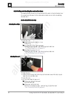
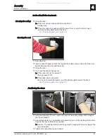
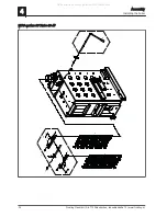
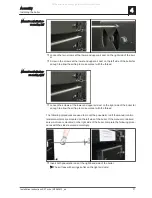
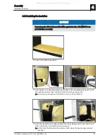
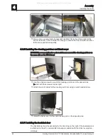
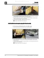
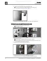
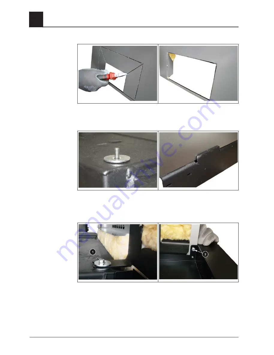
❒ Cut the perforated plates for the cleanout opening on both sides and bend them

inward

➥ Caution: bend the plates > 100° inward!


❒ Place one large spacer washer on each of the threaded bolts to the right and the

left above on the boiler

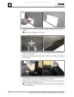
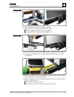
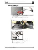
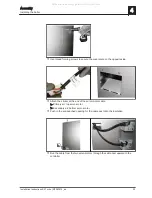
❒ Insert the insulating side panels at the base of the boiler at the flap and push them

onto the boiler


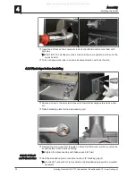
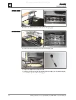
❒ Position the side panels with the door bracket onto the threaded bolts and secure

them lightly with a large and a small spacer washer and nut (1)

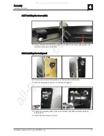
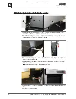
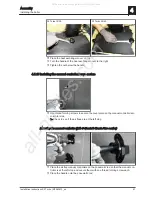
❒ Hang the upper spacer plate on the rivets between the insulating side panels and

attach with a thread forming screw (2)

➥ At the same time, this procedure also secures the bracket to the insulating side

panels at the front


4

Assembly

Installing the boiler

40

Froeling GesmbH | A-4710 Grieskirchen, Industriestraße 12 | www.froeling.at

All manuals and user guides at all-guides.com

Summary of Contents for S3 Turbo 18

Page 1: ...ons for technicians Read and follow the instructions and safety information Technical changes typographical errors and omissions reserved M1080813_en Edition 30 09 2013 Froeling GesmbH A 4710 Grieskirchen Industriestraße 12 www froeling at All manuals and user guides at all guides com a l l g u i d e s c o m ...

Page 2: ...ta for planning the flue gas system 13 3 Technology 14 3 1 Dimensions 14 3 2 Components and connections 15 3 3 Technical specifications 16 4 Assembly 19 4 1 Materials supplied 19 4 1 1 Tools required 19 4 2 Positioning 20 4 2 1 Temporary storage 20 4 3 Setting up in the boiler room 21 4 3 1 Remove boiler from pallet 21 4 3 2 Moving the boiler in the boiler room 21 4 3 3 Minimum distances in the bo...

Page 3: ...n and wiring 54 4 6 1 S Tronic control 54 Power connection 54 Hydraulic system 57 4 6 2 S Tronic Plus S Tronic Lambda control 58 Power connection 58 Hydraulic system 58 4 6 3 Information on circulating pumps 59 4 6 4 Concluding work 59 4 7 Connecting the hydraulic safety devices 61 5 Start up 62 5 1 Before commissioning configuring the boiler 62 5 2 Initial startup 63 5 2 1 Permitted fuels 63 Fire...

Page 4: ...ictures and content If you discover any errors please let us know doku froeling com Subject to technical change The EC Declaration of Conformity is only valid in conjunction with a delivery certificate which has been filled in correctly and signed as part of the commissioning process The original document remains at the installation site Commissioning installers or heating engineers are requested ...

Page 5: ... to serious injury or death You must follow the instructions WARNING The dangerous situation may occur and if measures are not observed it will lead to serious injury or death Work with extreme care CAUTION The dangerous situation may occur and if measures are not observed it will lead to minor injuries or damage to property Safety 2 Hazard levels of warnings Installation Instructions S3 Turbo M10...

Page 6: ...ing technician building technician Electrical installation technician Froling customer services The assembly staff must have read and understood the instructions in the documenta tion 2 3 Protective equipment for assembly staff You must ensure that staff have the protective equipment specified by accident pre vention regulations For transportation setup and assembly suitable workwear protective gl...

Page 7: ...els Standards for structural and safety devices ÖNORM H 5170 Heating installation Requirements for construction and safety engineering as well as fire prevention and environmental pro tection Standards for heating water ÖNORM H 5195 1 Prevention of damage by corrosion and scale formation in closed warm water heating systems at operating temperatures up to 100 C Austria VDI 2035 Sheet 1 Prevention ...

Page 8: ...haracteristics There must not be a potentially explosive atmosphere in the boiler room as the boiler is not suitable for use in potentially explosive environments The boiler room must be frost free The boiler does not provide any light so the customer must provide sufficient light ing in the boiler room in accordance with national workplace design regulations When using the boiler over 2000 metres...

Page 9: ...R no 412 NOTICE Note on filling with make up water Always bleed the filling hose before con necting in order to prevent air from entering the system Observe the standards and also follow the recommendations below Max cumulative value for alkaline earth 1 0 mmol l or 100 mg l corresponds to 5 6 dH Use softened water as the make up water Avoid leaks and use a closed heating system to maintain water ...

Page 10: ...gh If the pressure drops below a preset value the pump draws water from the receiving tank and feeds it back into the heating system Pump controlled pressure maintenance systems with open expan sion tanks e g without a diaphragm introduce ambient oxygen via the surface of the water exposing the connected system components to the risk of corrosion These systems offer no oxygen removal for the purpo...

Page 11: ...al heat out put can be dissipated to the building being heated under partial load conditions The storage tank capacity can be calculated according to EN 303 5 2012 using the fol lowing formula VSp 15TB x QN 1 0 3 x QH Qmin VSp QN TB QH Qmin Storage tank capacity in l Nominal heat output of boiler in kW Burn off period of boiler in h 1 Heating load of building in kW Minimum heat output of boiler in...

Page 12: ...at storage tank with a capacity of 12 litres per litre of fuel loading chamber is recommended Recommended storage tank capacity Unit S3 Turbo 18 28 S3 Turbo 36 45 Recommended storage tank capacity1 l 1700 3000 1 Values for calculating the capacity can be found in the technical data or the technical data with partial load inspection if available For the correct dimensions of the storage tank and th...

Page 13: ...s and other statutory regulations also apply NOTICE The chimney must be authorised by a smoke trap sweeper or chimney sweep Draught limiter The installation of a draught limiter is recommended NOTICE Install the draught limiter directly under the mouth of the flue line as the pressure is constantly low at this point Boiler data for planning the flue gas system Description S3 Turbo 18 28 36 45 Flue...

Page 14: ...or 680 780 H Height boiler 1470 1570 H1 Total height incl flue gas nozzle 1530 1630 H2 Height flue gas pipe connection 1750 1850 H3 Height flow connection 1280 1380 H4 Height return connection 140 140 H5 Height safety battery connection 890 970 H6 Height drainage connection 120 120 3 Technology Dimensions 14 Froeling GesmbH A 4710 Grieskirchen Industriestraße 12 www froeling at All manuals and use...

Page 15: ...1 2 5 Immersion sleeve for thermal discharge valve sup plied by the customer inches 1 2 6 Immersion sleeve for boiler sensor and STL inches 1 2 7 Flue gas pipe connection mm 150 8 Flue gas temperature sensor connection inches 1 2 9 Broadband probe connection inches 3 4 Technology 3 Components and connections Installation Instructions S3 Turbo M1080813_en 15 All manuals and user guides at all guide...

Page 16: ... level 80 100 Description S3 Turbo 36 S3 Turbo 45 Nominal output range kW 36 18 36 45 22 5 45 Electrical connection 230V 50Hz fused C13A Power consumption at nominal load W 45 75 65 75 Power consumption in slumber mode 3 3 Weight of boiler incl insulation and control kg 610 620 Total boiler capacity water L 190 190 Water pressure drop ΔT 10 20 K mbar 7 0 2 1 22 0 6 3 Minimum boiler return temperat...

Page 17: ...t mg m 11 10 1 Emissions values based on dry flue gas at standard temperature and pressure 0 C 1013 mbar with a volume content of oxygen of 13 Description S3 Turbo 36 S3 Turbo 45 Testing institute TÜV Austria1 TÜV Austria1 Test report no 11 UW Wels EX 128 42 11 UW Wels EX 128 5 Date of issue 21 07 2011 07 11 2011 Boiler class as per EN 303 5 2012 4 5 Boiler efficiency nominal load partial load 93 ...

Page 18: ...s values based on dry flue gas at standard temperature and pressure 0 C 1013 mbar with a volume content of oxygen of 13 3 Technology Technical specifications 18 Froeling GesmbH A 4710 Grieskirchen Industriestraße 12 www froeling at All manuals and user guides at all guides com ...

Page 19: ... Ash shovel 11 Cleaning kit 12 Cleaning brush small 13 Cleaning brush large Not pictured Installation and operating instructions guarantee certificate identification plate 4 1 1 Tools required The following tools are required for assembly Spanner or box wrench set widths across flats 8 32 mm Allen key set Flat head and cross head screwdrivers Hammer Diagonal cutting pliers Half round file Power dr...

Page 20: ...ught in on the pallet Remove the cardboard and remove the boiler from the pallet See Remove boiler from pallet page 21 Positioning using a crane Attach the crane hook to the attachment point correctly and position the boiler 4 2 1 Temporary storage If the system is to be assembled at a later stage Store components at a protected location which is dry and free from dust Damp conditions and frost ca...

Page 21: ...t TIP Use Froling s KHV 1400 boiler lifting system to help remove the pallet 4 3 2 Moving the boiler in the boiler room Position a fork lift or similar lifting device with a suitable load bearing capacity at the base frame Lift and transport to the intended position in the installation room Observe the minimum distances in the boiler room Assembly 4 Setting up in the boiler room Installation Instr...

Page 22: ...ce side of boiler to wall 200 800 1 1 The side of the boiler where the WOS lever is located B or D should be at least 800 mm from the wall to allow easy access for connecting the appliance and for maintenance work e g induced draught 4 4 Before Installation 4 4 1 Changing door stops as needed The boiler comes with the door stop on the right To change the side the door stops are on proceed as follo...

Page 23: ...r washers and nuts on the other side Only partially tighten the nuts NOTICE When changing the stop of the fuel loading door at this point the fuel load ing door must be converted See Converting the fuel loading door page 24 Rotate the door and rehang it with the stop on the other side Secure at the top and bottom with the hinge pins Refit the retainers to the top and bottom hinge pins To do so you...

Page 24: ...n the nuts at the top and the bottom on the side of the door with the stop NOTICE When the door stops have been changed you must check the settings and seal of the door See Setting and checking the seal on the doors page 26 Converting the fuel loading door Remove the radiation plate together with the seal 4 Assembly Before Installation 24 Froeling GesmbH A 4710 Grieskirchen Industriestraße 12 www ...

Page 25: ... the door handles The example below shows how to mount the fuel loading door handles The procedure is the same for mounting the handles of the combustion chamber door and the pre heating chamber door Position the door handle in the hole provided Insert flange bushing into door handle and secure it Assembly 4 Before Installation Installation Instructions S3 Turbo M1080813_en 25 All manuals and user...

Page 26: ...ap of 3 cm Setting must be corrected push the hinge toward the front See Positioning the doors page 27 Open the door Insert a sheet of paper at both the top and the bottom area of the door stop be tween the door and the boiler Close the door Try to pull the sheet of paper out If the paper cannot be removed the door seal is OK If the paper can be removed the door is not sealed properly push the hin...

Page 27: ...r seal is OK If the paper can be removed the door is not sealed properly push the locking plate toward the back See Positioning the doors page 27 Positioning the doors Using an Allen key 13 mm loosen the nuts on the locking plate and or hinge at the top and bottom Use suitable tools e g screwdriver and hammer to move the locking plate and or hinge to the rear or the front as needed Caution The loc...

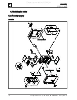
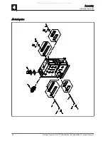
Page 28: ... 14 16 17 18 19 22 20 23 3 24 28 29 26 27 1 4 4 25 16 32 30 30 31 31 21 A Detail A 36 37 33 34 22 21 35 15 31 41 41 40 38 39 4 4 S3 Turbo 18 28 4 Assembly Installing the boiler 28 Froeling GesmbH A 4710 Grieskirchen Industriestraße 12 www froeling at All manuals and user guides at all guides com ...

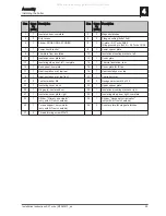
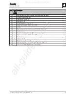
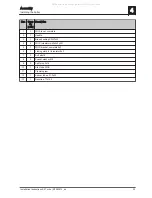
Page 29: ... 1 Heat insulation mat top rear 18 1 Heat insulation mat top 19 1 Heat insulation mat top front 20 1 Controller cover 21 2 Contact washer M4 22 2 Hexagonal screw M6 x 100 23 1 Insulating cover back 24 1 Upper spacer plate 25 1 Hinge pin insulated door 26 1 Insulation mounting brackets right 27 1 Insulation cover plate right 28 1 Insulating side panel right complete 33 1 Sticker Primary air actuato...

Page 30: ... 7 8 9 11 12 8 6 7 11 12 13 13 8 8 14 14 14 14 15 15 1 22 21 22 10 9 10 4 Assembly Installing the boiler 30 Froeling GesmbH A 4710 Grieskirchen Industriestraße 12 www froeling at All manuals and user guides at all guides com ...

Page 31: ...oller for air control system S Tronic S Tronic Plus 10 2 Handle black 11 2 Air duct secondary air left and right 12 2 Rubber seal for profile 12x2x15x23 L 1000 13 2 Pneumatic rods 14 4 Split pin ø3 2x20 15 2 Pressure spring ø17 8x1 1x28 21 1 Induced draught cable incl rotation speed transducer cable 2m 22 2 Servo motor LM 24AP5 F 300 1 S Tronic Lambda Assembly 4 Installing the boiler Installation ...

Page 32: ...stem S3 Turbo 18 28 1 2 3 4 6 7 7 8 9 9 8 10 11 12 13 5 4 Assembly Installing the boiler 32 Froeling GesmbH A 4710 Grieskirchen Industriestraße 12 www froeling at All manuals and user guides at all guides com ...

Page 33: ...OS bracket complete 6x3 6 1 Linking plate for turbulator 6x3 7 2 Bolt ø8x16 8 2 Spacer washer M8 9 2 Split pin ø2x16 10 1 Stay tube WOS 11 1 Clamping jaw 12 1 Spacer tube ø21 3x50 13 1 Rosette ø77x15 5 Assembly 4 Installing the boiler Installation Instructions S3 Turbo M1080813_en 33 All manuals and user guides at all guides com ...

Page 34: ...bo 36 45 2 3 1 4 6 7 6 9 9 10 11 10 11 12 9 9 8 4 10 11 10 11 5 13 4 Assembly Installing the boiler 34 Froeling GesmbH A 4710 Grieskirchen Industriestraße 12 www froeling at All manuals and user guides at all guides com ...

Page 35: ...1 WOS bracket complete 6x3 6 2 Linking plate for turbulator 6x3 7 1 Stay tube 8 1 Clamping jaw 9 4 Bolt ø8x16 10 4 Split pin ø2x16 11 4 Spacer washer M8 12 1 Spacer tube ø21 3x91 13 1 Rosette ø77x15 5 Assembly 4 Installing the boiler Installation Instructions S3 Turbo M1080813_en 35 All manuals and user guides at all guides com ...

Page 36: ...boiler and mount it with the four screws Caution Do not overstress the flange 4 5 4 Installing the pneumatic rods for the primary and secondary air Manual controllers or servo motors can be mounted on either the left or the right side on the boiler Remove the split pin on both pneumatic rods opposite the spring and pull one of the air flaps off of each 4 Assembly Installing the boiler 36 Froeling ...

Page 37: ...dures are used to mount the pneumatic rod if the manual control lers servo motors are mounted on the left side of the boiler If the manual controllers servo motors are mounted on the right side of the boiler complete the following proce dures with the sides reversed accordingly Insert both pneumatic rods at the right hand side of the boiler The air flaps with springs lie flat on the right air duct...

Page 38: ...evice sen sor Detach blanking plate for the side cleaning port Remove the screw cap from the side on which the WOS lever will be mounted lat er and replace it with a brass bushing Tighten the brass bushing with Allen wrench 27 mm Seal the broadband probe connection with a 3 4 blanking plug 2 On the S3 Turbo with S Tronic Lambda the broadband probe will be mounted here later Only for S Tronic and S...

Page 39: ...ht and secure them with three thread forming screws each Insert the cover plates such that the rivet 1 is at the bottom Insert the insulation mounting brackets at both insulating side panels and secure them with the two top thread forming screws 1 At the front the bracket will be secured later when the upper spacer plate is inserted Assembly 4 Installing the boiler Installation Instructions S3 Tur...

Page 40: ...e boiler Position the side panels with the door bracket onto the threaded bolts and secure them lightly with a large and a small spacer washer and nut 1 Hang the upper spacer plate on the rivets between the insulating side panels and attach with a thread forming screw 2 At the same time this procedure also secures the bracket to the insulating side panels at the front 4 Assembly Installing the boi...

Page 41: ...rear thermal insulation on the rear side of the boiler Insert insulating back panel over induced draught fan Secure the insulating back panel to the left and right with nine thread forming screws each Install the cover plates for ID fan Assembly 4 Installing the boiler Installation Instructions S3 Turbo M1080813_en 41 All manuals and user guides at all guides com a l l g u i d e s c o m ...

Page 42: ... insulating side panels to the right and left at the flap on the boiler base with thread forming screws Measure the diagonals and align the insulating side panels so that the two diago nals are the same Adjust the position of the side panels if necessary Tighten the nuts on the two brackets of the insulating side panels at the top on the boiler Position the control on top 4 Assembly Installing the...

Page 43: ...top Put the top heat insulation mat on The heat insulation mat must touch the front sheet Place the controller box on the boiler Use eight thread forming screws incl contact washers 1 to install controller box on the cable duct of the side panels Assembly 4 Installing the boiler Installation Instructions S3 Turbo M1080813_en 43 All manuals and user guides at all guides com ...

Page 44: ... cleaning port door on the desired side Start with the screws at upper right Attach the door handle for the cleaning port door using a round headed screw Install the blank cover for the side cleaning port on the opposite side 4 5 11 Installing the insulated door The illustrations show the assembly for the door stop on the right If the insulated door is attached on the left complete the following p...

Page 45: ... and lightly tighten the two hexagonal screws M6x12 Measure the distance from the insulating side panel to the centre of the borehole for the insulated door on the upper bracket Measure the distance from the insulating side panel to the centre of the borehole on the lower door bracket The two distances must be equal If necessary correct the position of the lower door bracket S3 Turbo 18 28 S3 Turb...

Page 46: ...e of the insulated door with the stop Mount the insulated door onto the lower door bracket using the hexagonal screw Attach the insulated door to the upper door bracket with hinge pin 1 Insert the hinge pin through the control and the upper door bracket 4 Assembly Installing the boiler 46 Froeling GesmbH A 4710 Grieskirchen Industriestraße 12 www froeling at All manuals and user guides at all guid...

Page 47: ...ated door is the same size along the entire height of the boiler If necessary correct the position of the lower door bracket 4 5 12 Fitting the sensors Screw in the brass bushing for the flue gas temperature sensor Make sure that the borehole with the thread is situated at the upper area of the brass bushing Assembly 4 Installing the boiler Installation Instructions S3 Turbo M1080813_en 47 All man...

Page 48: ... Install the broadband probe only with S Tronic Lambda Unscrew the pre installed bushing from the broadband probe Screw the bushing into the flue gas nozzle and gently tighten Screw the broadband probe into the bushing and gently tighten using an Allen wrench 22 mm Plug in the extension cable for the Lambda probe and un the cable through the ca ble duct to the controller box Tuck any extra cable i...

Page 49: ...the WOS lever S3 Turbo 18 28 S3 Turbo 36 45 Remove the heat exchanger cover Hang the WOS turbulators on the linking plate of the stay tube Make sure that you fit the turbulators in the right direction Hold the linking plate with the edge toward the top Hang the WOS turbulators over the edge Assembly 4 Installing the boiler Installation Instructions S3 Turbo M1080813_en 49 All manuals and user guid...

Page 50: ...cer tube at the stay tube Push the WOS lever through the distance and stay tubes from the outside and se cure it at the stay tube with a clamping jaw S3 Turbo 18 28 S3 Turbo 36 45 4 Assembly Installing the boiler 50 Froeling GesmbH A 4710 Grieskirchen Industriestraße 12 www froeling at All manuals and user guides at all guides com ...

Page 51: ...ser vo motor side Check to see if the air flaps are at the left stop Mounting the manual controller with S Tronic S Tronic Plus control Place the air flap manual controllers on the pneumatic rod so that the manual con troller is at the left stop and secure them with one thread forming screw each Place the handle onto the pneumatic rod Assembly 4 Installing the boiler Installation Instructions S3 T...

Page 52: ...ir flaps are closed Set the servo motors Set the direction of rotation of the servo motor 1 to left L Press the unlock key 2 and turn the drive for the shaft to the air duct 3 in an anti clockwise direction as far as the stop Place the servo motors onto the pneumatic rod Position the torque support and partially tighten the screws Align the servo motors so that they are straight and tighten the sc...

Page 53: ...ir top servo motor Secondary air bottom servo motor Push in the pre punched opening for the cable duct onto the insulation Run the cable from the two servo motors through the cable duct upward to the controller Assembly 4 Installing the boiler Installation Instructions S3 Turbo M1080813_en 53 All manuals and user guides at all guides com ...

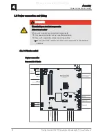
Page 54: ...t by a qualified electrician Observe the applicable standards and regulations Work must not be carried out on electrical components by unauthorised persons 4 6 1 S Tronic control Power connection Core module S Tronic 4 Assembly Power connection and wiring 54 Froeling GesmbH A 4710 Grieskirchen Industriestraße 12 www froeling at All manuals and user guides at all guides com ...

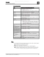
Page 55: ...gth Door switch TCS 9 Connection cable1 2 x 0 75mm2 Sensor 10 11 Connection cable1 2 x 0 75mm2 shielded from 25m cable length Return sensor RTS 12 Connection cable1 2 x 0 75mm2 Boiler sensor BS 13 PWM 0 10V pump 1 14 Induced draught 15 Connection cable1 5 x 1 5mm2 Pump 1 on core module 16 Connection cable1 3 x 1 5mm2 max 1 5A 280W 230V Mains 17 Connection cable 1 3 x 1 5 mm2 fused with 16A provide...

Page 56: ...ch and display Connect the door switch Insert the door switch and display Connect the flue gas temperature sensor green yellow red blue Core module Connect the flue gas temperature sensor 4 Assembly Power connection and wiring 56 Froeling GesmbH A 4710 Grieskirchen Industriestraße 12 www froeling at All manuals and user guides at all guides com a l l g u i d e s c o m ...

Page 57: ...c layered tank H2 Connections are represented schematically Sonde 2 Pump 1 Note Controller S Tronic Weather activated heating circuit control externally Balancing valve Hygienic layered tank H2 Mains supply 230V External sensor Flow temp sensor 1 2 Heating circuit 1 2 Mot mixing valve 1 2 Domestic hot water Cold water Temp sensor 2 Assembly 4 Power connection and wiring Installation Instructions S...

Page 58: ...nents have been wired Wire the mains connection in the controller box The power supply line mains connection must be fitted with a max C13A fuse by the customer Observe the circuit diagrams in the boiler controller operating instructions Hydraulic system Possible non binding planning suggestion M M M M Room sensor Option External sensor Mains supply 230V Log wood boiler S3 Turbo Pump assembly FE P...

Page 59: ...utputs of the boards Observe the connection instructions in the boiler controller documentation CAUTION When using high efficiency pumps without an additional control line at speed con trolled pump outputs Malfunctions of the boiler the pump and the hydraulic system may occur Therefore Do not connect EC motor pumps without a control line to the speed controlled pump outputs of the boards Only use ...

Page 60: ...e the controller cover with 2 screws and contact washers Put on the back heat insulation mat Put on the rear insulating cover 4 Assembly Power connection and wiring 60 Froeling GesmbH A 4710 Grieskirchen Industriestraße 12 www froeling at All manuals and user guides at all guides com ...

Page 61: ... valve 2 Safety valve Safety valve as per prEN 1268 1 with a diameter of DN15 The safety valve must be installed in an accessible place on the heat generator or in direct proximity in the flow pipe in such a way that it cannot be shut off 3 Return temperature control with pump 4 Diaphragm expansion tank The diaphragm pressurised expansion tank must conform to EN 13831 and hold at least the maximum...

Page 62: ...iler control unit Check the system pressure of the heating system Check that the heating system is completely vented Check that the safety devices are present and working correctly Check that there is sufficient ventilation in the boiler room Check the seal of the boiler All doors and inspection openings must be tightly sealed Check that drives and actuators are working and turning in the right di...

Page 63: ...ad of in forest Walls of buildings facing the sun are ideal If possible stock fuel for the day in a warm place e g in boiler room pre heats the fuel NOTICE Use fuels that are consistent in size and water content NOTICE Burning extremely dry fuels w 15 may require repairs by qualified staff Please contact Froling customer services or your installer 5 2 2 Fuels permitted under certain conditions Woo...

Page 64: ...guarantee Using non standard fuels can also lead to serious problems with combustion For this reason when operating the boiler Only use permitted fuels 5 2 4 Heating up for the first time CAUTION If the boiler heats up too quickly on initial start up If the output during the heating up process is too great the combustion chamber may be damaged as a result of drying out too rapidly For this reason ...

Page 65: ... Lambda control Open the insulated door and the fuel loading door Fill the fuel loading chamber for initial start up and heat up NOTICE See boiler operating instructions Boiler with manual controller 0 100 50 Set the manual controller for the air flap as shown in the table below NOTICE The information below only applies to split wood and not for round timber square timber etc Start up 5 Initial st...

Page 66: ...t be used as standard values for operating the boiler The terms used i e long split wood edge length EL 10 cm and short split wood edge length EL 10 cm have been defined in these instructions by Froling there is no fuel standard or similar guidelines Open the insulated door and the fuel loading door Fill the fuel loading chamber for initial start up and heat up NOTICE See boiler operating instruct...

Page 67: ...ffect Setting More secondary air Greater O2 content Rotate manual controller clockwise plus direction Less secondary air Lower O2 content Rotate manual controller counter clock wise minus direction Correct the air flap for secondary air lower air flap to reach the required O2 con tent NOTICE The manual controller should be set so that the O2 content is between 8 and 11 Once the manual controller h...

Page 68: ...tion against frost 6 2 Disassembly To disassemble the system follow the steps for assembly in reverse order 6 3 Disposal Ensure that the system is disposed of in an environmentally friendly way in ac cordance with waste management regulations You can separate and clean recyclable materials and send them to a recycling centre The combustion chamber must be disposed of as builders waste 6 Decommissi...

Page 69: ...7 Appendix 7 1 Pressure equipment regulation Appendix 7 Pressure equipment regulation Installation Instructions S3 Turbo M1080813_en 69 All manuals and user guides at all guides com ...

Page 70: ... 91 70 Organic hydrocarbons OGC mg MJ 3 20 Dust mg MJ 21 8 1 The pollutant concentration is specified as a mass based on the energy content of the fuel fed to the combustion system in mg MJ Test data Emissions in mg m 1 nominal load partial load Carbon monoxide CO mg m 118 714 Nitrogen oxide NOx mg m 134 102 Organic hydrocarbons OGC mg m 4 30 Dust mg m 30 12 1 Emissions values based on dry flue ga...

Page 71: ...striestraße 12 A 4710 Grieskirchen AUSTRIA TEL 0043 0 7248 606 0 FAX 0043 0 7248 606 600 INTERNET www froeling com 7 3 2 Address of the installer Stamp Appendix 7 Addresses Installation Instructions S3 Turbo M1080813_en 71 All manuals and user guides at all guides com a l l g u i d e s c o m ...

Reviews: