background image

3 | Notes for operating a heating system

20

B1510622_en | Operating instructions Firewood boiler S4 Turbo

3.4 Domestic hot water

Unless contrary to other national regulations, the latest versions of the following
standards and guidelines apply:

Austria:
Germany:

ÖNORM H 5195
VDI 2035

Switzerland:
Italy:

SWKI BT 102-01
UNI 8065

Observe the standards and also follow the recommendations below:

r

Aim for a pH value of between 8.2 and 10.0. If the central heating water comes into
contact with aluminium, the pH value must be between 8.2 and 9.0

r

Use prepared water which complies with the standards cited above for filling and
make-up water

r

Avoid leaks and use a closed heating system to maintain water quality during
operation

r

When filling with make-up water, always bleed the filling hose before connecting, in
order to prevent air from entering the system

r

The heating water must be clear and free from substances that lead to sediments.

r

With regard to corrosion protection, the use of fully demineralised filling and make-up
water with an electrical conductivity of up to 100 µS/cm is recommended in
accordance with EN 14868

Advantages of low-salt or fully demineralised water:

▪ Complies with the applicable standards

▪ Less of a drop in output due to reduced limescale build-up

▪ Less corrosion due to fewer aggressive substances

▪ Long-term cost savings thanks to improved energy efficiency

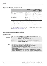
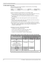
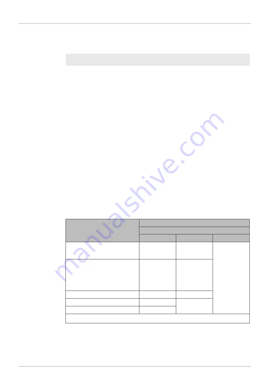
Filling and make-up water as well as heating water in accordance with VDI 2035:

Total heat output in kW

Total earth alkalis in mol/m³ (total hardness in °dH)

Specific system volume in l/kW heat output

1)

≤ 20

20 to ≤40

> 40

≤ 50


specific water content

heat generator ≥ 0.3 l/kW

2)

none

≤ 3.0 (16.8)

< 0.05 (0.3)

≤ 50


specific water content

heat generator < 0.3 l/kW

2)

(e.g. circulation water heater) and

systems with electric heating

elements

≤ 3.0 (16.8)

≤ 1.5 (8.4)

> 50 to ≤ 200

≤ 2.0 (11.2)

≤ 1.0 (5.6)

> 200 to ≤ 600

≤ 1.5 (8.4)

< 0.05 (0.3)

> 600

< 0.05 (0.3)

1. For calculating the specific system volume, the smallest individual heating capacity is to be used for systems with several heat generators.

2. In systems with several heat generators with different specific water contents, the smallest specific water content is decisive in each case.

Summary of Contents for S4 Turbo 15

Page 1: ...Firewood boiler S4 Turbo Translation of original German version of operating instructions for operators Read and follow all instructions and safety instructions All errors and omissions excepted B1510622_en Edition 02 11 2022 ...

Page 2: ...eous operation with other air drawing systems 19 3 4 Domestic hot water 20 3 5 Pressure maintenance systems 21 3 6 Return lift 22 3 7 Combination with storage tank 22 3 8 Chimney connection chimney system 22 4 Operating the System 23 4 1 Assembly and initial startup 23 4 2 Switching on the power supply 24 4 3 Before heating up the boiler 24 4 3 1 Clean the heat exchanger pipes 24 4 3 2 Check the i...

Page 3: ...ing 51 5 Servicing the system 52 5 1 General information on servicing 52 5 2 Required tools 53 5 3 Maintenance work by the operator 54 5 3 1 Inspection 54 5 3 2 Periodic inspection and cleaning 55 5 4 Servicing the condensing boiler heat exchanger optional 65 5 4 1 Inspecting the heat exchanger 65 5 4 2 Checking the condensation drain 67 5 5 Maintenance work by technicians 68 5 5 1 Cleaning the La...

Page 4: ...roling S4 Turbo is a wood boiler for the non condensing combustion of firewood The fuel loading chamber is filled with fuel via the fuel loading door located behind the heat insulated door on the front of the boiler The combustion grate through which the combustion gases are sucked into the combustion chamber by the induced draught fan is located below the fuel loading chamber When the induced dra...

Page 5: ...ber door with inspection glass 5 Lambdatronic S 3200 control Ü Overview of the touch display 32 6 Lever for heat exchanger cleaning system WOS 7 Actuators for automatic regulation of primary and secondary air 8 Automatic ignition optional 9 Back insulating cover 10 Heat exchanger cover Maintenance opening for cleaning the WOS system and heat exchanger 11 Main switch 12 Service port 13 STL high lim...

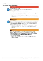
Page 6: ...nent and if measures are not observed it will lead to serious injury or death You must follow the instructions WARNING The dangerous situation may occur and if measures are not observed it will lead to serious injury or death Work with extreme care CAUTION The dangerous situation may occur and if measures are not observed it will lead to minor injuries NOTICE The dangerous situation may occur and ...

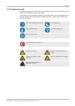
Page 7: ...ed directly within the danger area of the boiler indicate immediate hazards or safety procedures These stickers must not be removed or covered Refer to the operating instructions Wear safety shoes Wear protective gloves Turn off the main switch Keep the doors closed Unauthorised access prohibited Warning hot surface Warning hazardous electrical voltage Warning hazardous or irritant materials Warni...

Page 8: ...es such as insufficient combustion air or non standard fuel can cause serious faults in combustion e g spontaneous combustion of carbonisation gases or flash fires which can in turn cause serious accidents When operating the boiler please note the following r Instructions and information regarding versions and minimum values as well as standards and guidelines for heating components in the instruc...

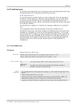
Page 9: ...oduct will need to undergo new hazard evaluation procedures by the operator The operator will then be fully responsible for the declaration of conformity according to the valid guideline s for the product and will need to issue a corresponding declaration for the device This person will then assume all of the rights and responsibilities of a manufacturer 2 4 1 Permitted fuels Firewood Firewood up ...

Page 10: ...air duct should be adjusted accordingly for optimal burning of these fuels w 15 Ü Extra cleaning of flue gas paths 74 2 4 2 Fuels permitted under certain conditions Wood briquettes Wood briquettes for non industrial use with a diameter of 5 10 cm and 5 50 cm long Note on standards EU Fuel as per EN ISO 17225 Part 3 wood briquettes class B D100 L500 Form 1 3 Additional for Germany Fuel class 5a 3 o...

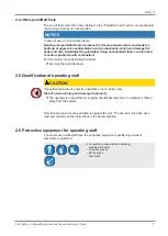
Page 11: ...combustion For this reason when operating the boiler r Use only the permitted fuels 2 5 Qualification of operating staff CAUTION If unauthorised persons enter the Installation room boiler room Risk of personal injury and damage to property r The operator is responsible for keeping unauthorised persons in particular children away from the system Only trained operators are permitted to operate the u...

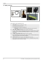
Page 12: ...inst overheating The STL switches off the combustion system when the boiler reaches 105 C The pumps continue to run Once the temperature falls below approx 75 C the STL can be reset mechanically TA THERMAL DISCHARGE VALVE protection against overheating The thermal discharge valve opens a valve at approx 100 C and feeds cold water to the safety heat exchanger to lower the boiler temperature SV SAFE...

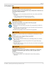
Page 13: ...k on the boiler and it should only be operated using the handles provided r Insulate the flue gas pipes and do not touch them during operation WARNING If you open the combustion chamber door pre heating door fuel loading door during operation This may result in injury damage or flue gas generation Take the following precautions r Do not open the combustion chamber door or pre heating chamber door ...

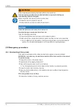
Page 14: ...arried out successfully Ä Due to differing fuel compositions Froling cannot guarantee successful automatic ignition The manufacturer supplier is not responsible for resulting damage 2 9 Emergency procedure 2 9 1 Overheating of the system If the system overheats and the safety devices fail to operate proceed as follows NOTICE Do not under any circumstances switch off the main switch or disconnect t...

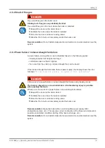
Page 15: ...nits e g induced draught fan can be heard If the induced draught fan fails when there is power supply the display shows the error message ID fan does not rotate in spite of full activation DANGER In the event of a power failure or induced draught fan failure during heating mode The boiler is placed in an uncontrolled state Life threatening injury is possible when opening the doors What to do in th...

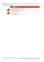
Page 16: ...ctions Firewood boiler S4 Turbo 2 9 4 Fire in the system DANGER In case of fire in the system Risk of death by fire and poisonous gases Emergency procedure in case of fire r Leave the boiler room r Close the doors r Inform the fire department ...

Page 17: ...ved The appropriate supervisory authority inspection agency must always be informed when installing or modifying a heating system and authorisation must be obtained from the building authorities Austria report to the construction authorities of the community or magistrate Germany report new installations to an approved chimney sweep the building authorities 3 2 Installation site Requirements for t...

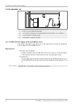
Page 18: ...om The system is operated in open flue mode i e the combustion air required to operate the boiler is drawn from the installation room Requirements Opening to the atmosphere Weather conditions must not affect the air flow in any way e g snow and foliage Cross section area free of obstructions such as cover gratings and slats Air supply lines For air supply lines longer than 2 metres and where mecha...

Page 19: ...that an approved under pressure monitoring system such as air pressure monitor P4 which monitor the maximum under pressure to 4 Pa must be installed in the installation room In addition at least one of the following three requirements must be met Source Section 4 MFeuV 2007 2010 Dimension the cross section of the combustion air opening so that when the boiler is in operation the maximum under pres...

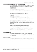
Page 20: ...of fully demineralised filling and make up water with an electrical conductivity of up to 100 µS cm is recommended in accordance with EN 14868 Advantages of low salt or fully demineralised water Complies with the applicable standards Less of a drop in output due to reduced limescale build up Less corrosion due to fewer aggressive substances Long term cost savings thanks to improved energy efficien...

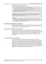
Page 21: ...tions caused by changes in the hot water temperature Two main systems are used Compressor controlled pressure maintenance In compressor controlled pressure maintenance units a variable air cushion in the expansion tank is responsible for volume compensation and pressure maintenance If the pressure is too low the compressor pumps air into the tank If the pressure is too high air is released by mean...

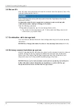
Page 22: ...ting some kind of control device e g thermometer 3 7 Combination with storage tank You can find more detailed information about storage tank design in the boiler assembly instructions NOTICE See Design Information section in the assembly instructions S4 Turbo 3 8 Chimney connection chimney system EN 303 5 specifies that the entire flue gas system must be designed to prevent wherever possible damag...

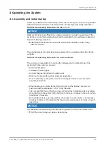
Page 23: ...he customer is responsible for ensuring the following prior to initial start up of the system by Froling customer services Electrical installation Installation of water pipes Connect flue gas including all insulation work Work must comply with local fire protection regulations Correct assembly setting of the air duct according to firewood used see boiler assembly instructions When heating up the b...

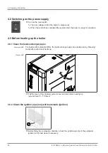
Page 24: ...3 Before heating up the boiler 4 3 1 Clean the heat exchanger pipes Automatic WOS For boilers with automatic WOS the heat exchanger pipes are cleaned using Cleaning mode after each time it heats up Manual WOS r Pull the lever of the cleaning system several times before heating up up and down 5 10 times 4 3 2 Check the ignition pipe only with automatic ignition r Before filling the combustion chamb...

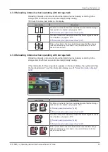
Page 25: ...mall amount In this case do not add fuel 4 3 4 Reloading intervals when operating with storage tank Reloading intervals and amounts should be determined exclusively according to the storage tank for efficient and environmentally friendly heating If the information for the storage tank appears on the basic display the symbol will show the tank load status To set the information display see Ü Select...

Page 26: ...quired to heat the boiler and heating system Requirements for function 1 Four temperature sensors installed in storage tank 2 Correct storage tank size specified 3 Reload quantity calculation activated The control displays the following menu when the insulating door is opened A B C Item Description A Graphic representation of required reload quantity B Fuel selection Soft wood Mixed wood Hardwood ...

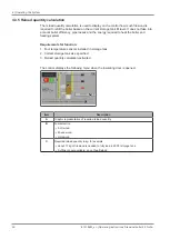
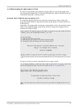
Page 27: ...we can use the simplified formula Q m x c x Δt Q energy required m mass of the medium to be heated c heat capacity of the medium to be heated constant for water Δt temperature difference between start and end temperature1 Mass m x heat capacity c x temperature difference Δt energy Q 2000 kg x 1 163 Wh kgK x 30 K 69 780 Wh 69 780 Wh 69 8 kWh Heating a 2 000 litre storage tank from 50 C to 80 C requ...

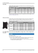
Page 28: ...water content of approx 20 Using our example above with beech the fill level of an S4 Turbo 34 would therefore be approx one third Fill level Weight at fill level S4 Turbo 15 28 S4 Turbo 32 60 3 3 Beech approx 45 kg approx 55 kg Spruce approx 28 kg approx 33 kg 2 3 Beech approx 30 kg approx 37 kg Spruce approx 19 kg approx 22 kg 1 3 Beech approx 15 kg approx 18 kg Spruce approx 9 kg approx 11 kg 4...

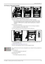
Page 29: ...r r Insert one layer of firewood Ä Use firewood with a length of approximately 50 cm and arrange it lengthwise Ä Do not completely cover the flame slot A r After the first layer of wood lay cardboard across the whole area r Fill the fuel loading chamber according to the expected consumption and close the fuel loading chamber door Ü Determining the right amount of fuel 27 r Open the pre heating doo...

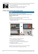
Page 30: ...ers from the combustion chamber r Allow the combustion chamber to cool down r An ash layer up to the middle row of holes in the combustion chamber guards facilitates the ignition process Activate the function automatic ignition to automatically heat up the boiler r Navigate to the Ignition menu and set the Automatic ignition parameter to YES r Open the insulated door and the fuel loading door Ä Th...

Page 31: ...roximately 50 cm and arrange it lengthwise r The burn out opening in the grate must remain free r Close the fuel loading door and insulated door Ä The boiler changes to preventilation status To guarantee a safe boiler operating status and to rule out possible ignition by residual embers due to incomplete cleaning of the combustion chamber the boiler attempts to reach Heating status within a specif...

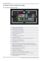
Page 32: ...nt by chimney sweep or regulatory body 71 F Display of the current operating status G View available functions in the quick menu Ü Quick menu 37 H Access all system information No parameters may be changed in the info menu I System menu for opening the system settings All parameters can be displayed and or edited depending on the user level Ü Navigation within the system menu 35 J Display and chan...

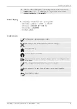
Page 33: ...status GREEN flashing interval 5 sec OFF 1 sec ON Off GREEN constant BOILER SWITCHED ON ORANGE flashing WARNING RED flashing FAULT Control icons Confirms values entered activates parameters Discards any values entered without saving and closes messages Back to basic display Accesses all system information Opens quick menu Selection of functions depending on user level configuration and current sta...

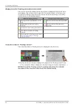
Page 34: ... not in use Remote control of the boiler is permitted Establishes connection to froeling connect Remote control of the boiler is not permitted Connection to the froeling connect server No network connection to froeling connect No connection to froeling connect server Ü Connection status to froeling connect 34 Connection status to froeling connect The connection status to froeling connect is displa...

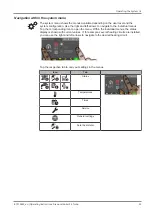
Page 35: ... left arrows to navigate to the individual menus Tap the corresponding icon to open the menu Within the individual menus the status display is shown with current values If for example several heating circuits are installed you can use the right and left arrows to navigate to the desired heating circuit Tap the respective tab to carry out settings in the menus Icon Tab Status Temperatures Times Ser...

Page 36: ... time window The desired time window can be set in the Times tab in the menus of the heating components heating water etc Up to four time windows are possible per day r Use the left or right arrow to navigate to the desired day of the week r Tap the time window or icon underneath the day of the week r Tap on the time window to be changed r Use the up and down arrows to set the start and end time a...

Page 37: ...rnal temperature heating limit set in the Heating menu is active and can prevent release of the heating circuits Extra loading One time extra loading of all available DHW tanks Subsequently the mode that was previously set becomes active again Error display List of all pending boiler faults and how to eliminate them Setting wizard Switching on for the first time Setting the language manufacturer s...

Page 38: ...in storeroom Heating circuit 01 18 Temperatures Display of the actual flow temperature and flow temperature setpoint of the respective heating circuit DHW tank 01 08 Temperatures Display of the current DHW tank temperature and control of DHW tank pump of the respective DHW tank Storage tank 01 04 Temperatures Display of storage tank temperature top and bottom 3 temperature sensors1 Display of stor...

Page 39: ...is possible to have an information display with storage tank temperatures in accordance with the number of sensors An information display that spans two areas is used 4 6 3 Change boiler mode Depending on the type of boiler there are several modes available which can be changed directly in the basic display of the touch display ...

Page 40: ...plied with heat within the selected loading times Heating circuits are switched off frost protection remains active Continuous load The boiler continuously maintains the selected boiler temperature setpoint and only shuts down for cleaning purposes Supply heating circuits and domestic hot water tanks with heat according to the selected heating times NOTICE Consult the enclosed operating instructio...

Page 41: ...ting instructions Firewood boiler S4 Turbo 41 4 6 4 Change date and time Tap on the displayed date and time to change the date and time in the basic display Use the up and down arrows to adjust the settings and tap on the Confirm icon to save ...

Page 42: ... r Tap the information display for the desired DHW tank r Tap the mode icon for the DHW tank r Tap the extra loading icon Ä One time loading of DHW tank starts Once the selected DHW tank temperature setpoint has been reached loading stops and the icon switches to automatic NOTICE If this selection is not configured in the information display in the basic display open the components in the system m...

Page 43: ...compensated by increasing reducing the flow temperature When starting up the system it is defined whether the heating circuit is operating as a high temperature circuit or a low temperature circuit The following values are set High temperature circuit Desired flow temperature at 10 C outside air temperature 60 C Desired flow temperature at 10 C outside air temperature 40 C Low temperature circuit ...

Page 44: ... of the heating curve at 10 C outside temperature see figure 2 Room temperature on warm days too high OK on cold days Change the slope of the heating curve Reduce the temperature level of the heating curve at 10 C outside temperature see figure 3 Figure 1 Figure 2 Figure 3 Depending on the situation the heating curve an be adapted by tapping or at 10 C outside air temperature If the heating curve ...

Page 45: ...ating circuit is switched off Frost protection remains active Auto The heating circuit is controlled according to the set time program Party The heating circuit is regulated before the start of the next heating time To cancel this function prematurely activate another mode function Setback mode The heating circuit is regulated to the set setback temperature until the start of the next heating time...

Page 46: ...l only the basic display appears It is not possible to change parameters Customer Code 1 Standard user level for normal operation of the controller All customer specific parameters are displayed and can be changed Installer Releases parameters to adjust the controller to the system components if configured All parameters are available Service 4 6 13 Change the name of the components The names of t...

Page 47: ...rmines a time period in which an active heating circuit is regulated for the set setback temperature and in which an activated boiler is not loaded If Legionella heating is set it remains active If the start date is set in the future the suitcase icon will be highlighted in green Once the set start time of the holiday program has been reached the boiler switches to holiday mode ...

Page 48: ...reviously activated mode water tap symbol domestic hot water water tap radiator symbol automatic 4 6 15 Activate automatic ignition r Tap the system menu in the basic display and navigate to the Ignition menu r Set Automatic ignition parameter to YES NOTICE Consult the enclosed operating instructions of the boiler controller for a detailed description of the adjustable parameters ...

Page 49: ...rom splinters r When working on the boiler during operation particularly when reloading fuel always wear protective gloves WARNING Opening the fuel loading door can cause injury damage and smoke r Open the fuel loading door slowly and with care r Close the fuel loading door again immediately after checking reloading r Open the fuel loading door slowly and check the fuel If the fuel in the boiler h...

Page 50: ...ler cool only then switch off the main switch Ä ID fan switches off when Off status has been reached flue gas temperature 80 C boiler temperature 65 C r Turn off the main switch Ä Boiler controller is switched off Ä There is no power supply to any of the boiler components NOTICE Frost protection function is no longer active 4 9 Checking the ash level in the boiler NOTICE Cracks in the combustion c...

Page 51: ... the insulated door and the pre heating chamber door r Scrape the ash from the fuel loading chamber into the combustion chamber using the furnace tool r Open the combustion chamber door r Remove the ash using the rounded ash shovel r Push the ash forwards out of the lower channel of the combustion chamber into the ash drawer provided using the furnace tool r Shovel the ash into container provided ...

Page 52: ... in on the boiler allow the fuel in the boiler to burn off r Allow boiler to cool off and switch off main switch WARNING When inspecting and cleaning the boiler with the main switch on Serious injuries possible due to boiler individual components starting up automatically induced draught Before inspection and cleaning work in on the boiler r Allow the fuel in the boiler to burn off r Allow boiler ...

Page 53: ...maintenance work Included in delivery 1 Furnace tool with bracket 2 Spanner for door mountings 3 Ash shovel 4 Ash drawer 5 Cleaning brush 30x20 for cleaning the carbonisation gas duct 6 Cleaning brush Ø54 for cleaning the heat exchanger Not included 7 Spanner or box wrench AF 13 8 Screwdriver set Philips flat head Torx T20 9 Small brush or cleaning brush 10 Ash vacuum ...

Page 54: ...n tank match your installer s specifications If the system pressure decreases r Top up with water NOTICE If this happens frequently the seal of the heating system is faulty Inform your installer If large pressure fluctuations are observed r Ask an expert to inspect the expansion tank Checking the thermal discharge safety device r Check the seal of the discharge valve Ä The discharge pipe must not ...

Page 55: ...ing hours and fuel quality Inspection and cleaning must be repeated after not more than 1500 operating hours or at least once a year For less efficient fuels e g high ash content this work needs to be carried out more frequently Cleaning the carbonisation gas duct r Open the insulated door and the fuel loading chamber door r Switch off the induced draught fan Ä This prevents damage to the fan from...

Page 56: ...de plate and clean the slits Ä For cleaning use the door adjusting spanner provided if suitable Cleaning the heat exchanger pipes S4 Turbo 22 40 r Lift off the back insulating cover and remove the heat exchanger cover Ä Use spanner A provided r Remove the pipe locking pin B and take out the WOS lever r Lift out the turbulators together with the mounting bracket ...

Page 57: ...nel of the combustion chamber into the ash drawer provided using the furnace tool S4 Turbo 34 40 S4 Turbo 50 60 S4 Turbo 15 28 r Before fitting in the heat exchanger pipes check that the WOS springs are correctly hooked into the linking plate Ä The protruding canted sheet metal strips must face upwards and the turbulators must be attached as shown r Thread the turbulators into the heat exchanger p...

Page 58: ...he back insulating cover and remove the heat exchanger cover Ä Use spanner A provided r Remove both pipe locking pins B r Pull out WOS lever and remove cover plate C r Remove blanking plugs D and pull out the WOS shaft behind r Loosen carrier plate E and lift out the turbulators together with the mounting bracket ...

Page 59: ...nnel of the combustion chamber into the ash drawer provided using the furnace tool r Before fitting in the heat exchanger pipes check that the WOS springs are correctly hooked into the linking plate Ä The protruding canted sheet metal strips must face upwards and the turbulators must be attached as shown r Thread the turbulators into the heat exchanger pipes and connect to carrier plate r Insert t...

Page 60: ... remove the flue gas temperature sensor from the flue gas pipe r Wipe the flue gas temperature sensor with a clean cloth r Push in the flue gas temperature sensor until about 20 mm of the sensor remains protruding from the bushing and secure with fixing screw S4 Turbo 50 60 r Remove the cover behind the flue gas pipe nozzles and induced draught cover plates r Undo the screws on the top and pull th...

Page 61: ...ut 20 mm of the sensor remains protruding from the bushing and secure with fixing screw Cleaning the flue gas pipe Switch off the induced draught fan This prevents damage to the fan by the cleaning brush r Remove the inspection cover on the connecting pipe r Clean the connecting pipe between the boiler and chimney with a chimney sweeping brush Ä Depending on how the flue gas pipes and chimney drau...

Page 62: ...ired r Unplug the connection cable of the induced draught fan r Remove the induced draught fan from the back of the boiler Ä Take care not to damage the seal r Check running wheel for damage r Clean the fan wheel from the inside out using a soft brush or paint brush NOTICE Do not move the balancing weights on the blower wheel r Remove dirt and deposits from the induced draught housing using a scra...

Page 63: ...of paper at both the top and the bottom of the door stop between the door and the boiler r Close the door and try to pull out the sheets of paper Ä If the paper can be removed door is not sealed properly and must be adjusted Adjusting the doors r Loosen the locknuts A AF 13 on the locking cams r Press door onto door frame and adjust the contact pressure using the locking cam B Ä Adjusting spanner ...

Page 64: ...tom of the locking plate and set the contact pressure on the door handle side r Use suitable tools e g screwdriver and hammer to move the locking plate towards the back or the front as required Ä CAUTION The hinge must be aligned in the same way at the top and bottom r Secure the adjustments by tightening the lock nuts A ...

Page 65: ... or at least once a month For less efficient fuels e g high ash content this work needs to be carried out more frequently 5 4 1 Inspecting the heat exchanger When the boiler has cooled off r Remove the top cover on the condensing boiler heat exchanger r Remove the inspection cover incl cleaning system below and check the heat exchanger for dirt r Place the inspection cover back on the heat exchang...

Page 66: ... from above Depending on the design the access panel on the back of the condensing boiler heat exchanger may be removed r Unplug the induced draught fan cable and pull it out of the back panel r Remove the cover plate for ID fan and back panel r Remove the cover plate and seal from the condensing boiler heat exchanger r Check the inside of the condensing boiler heat exchanger B and drain C for dep...

Page 67: ...d in turn lead to problems with combustion For this reason it is important to check the condensation drain regularly At the back of the boiler below the condensing boiler heat exchanger r Position a suitable container below the siphon to catch the condensation that runs out r Remove and check the siphon for dirt and deposits r Check the condensation drain up to where it enters the waste water syst...

Page 68: ...nce and servicing by a heating specialist will ensure a long trouble free service life for your heating system It will ensure that your system stays environmentally friendly and operates efficiently and cost effectively In the course of this maintenance the entire system is inspected and optimised particularly regulation and control of the boiler The emission measurement carried out can also be us...

Page 69: ...ating instructions Firewood boiler S4 Turbo 69 5 5 1 Cleaning the Lambda probe S4 Turbo 22 40 r Remove the back insulating cover and thermal insulation upwards S4 Turbo 50 60 r Remove the cover plates for ID fan A rear cover B und housing C ...

Page 70: ...rush and ash vacuum Ä Hold the Lambda probe with the tip downwards so that deposits can fall out of the measuring ports r Check the adapter 2 and plastic bushing 3 for dirt and cracks replace if necessary Ä IMPORTANT The seal surface of the plastic bushing must lie flat after assembly CAUTION Do not clean the Lambda probe with compressed air Do not use chemical cleaning agents brake cleaner etc Ha...

Page 71: ... for the duration of the measurement r There must be a suitable measuring port in the straight flue gas pipe for the measurement The measuring port must be twice the flue gas pipe diameter away from the last upstream bend Ä If the measuring port is not correctly positioned the measuring result will be distorted 5 6 1 General information on measurement Observe the following basic conditions r Only ...

Page 72: ...guards must be visible r Close the fuel loading door Once the basic firebed has been achieved top row of holes visible in the combustion chamber guards the two lower rows of holes of the combustion chamber guards are covered with embers r With the doors closed press the chimney sweep button boiler with button display or activate chimney sweep function boiler with touchscreen and select the menu it...

Page 73: ...lace components or parts with original replacement parts 5 8 Disposal information 5 8 1 Disposal of the ash Austria r dispose of ash in accordance with the Waste Management Act AWG Other countries r dispose of ash in accordance with local regulations 5 8 2 Disposal of system components r Ensure that they are disposed of in an environmentally friendly way in accordance with waste management regulat...

Page 74: ...ng to the specified program r After a power failure check whether the STL high limit thermostat has tripped r Keep the doors of the boiler closed during and after the power failure at least until the induced draught fan automatically starts up again 6 2 Extra cleaning of flue gas paths Error characteristics Possible cause Elimination of error Extra cleaning required due to very sticky black deposi...

Page 75: ... yet been cleared r Status LED indicates the nature of the fault Orange flashing Warning Red flashing Error or alarm r A fault message is shown on the display The term fault is a collective term for warnings errors and alarms The boiler reacts differently to the three types of message WARNING In case of warnings the boiler initially continues controlled operation giving the option of resolving the...

Page 76: ...lows Open error display System menu Diagnostics Current fault list The error display lists all current faults r Open by tapping the listed fault r The Message tab displays the current fault r Press the Error resolution tab to view possible causes and troubleshooting procedures r Tap the Cancel icon to close the current fault and display the fault list r Tap the Cancel icon again and confirm that y...

Page 77: ...B1510622_en Operating instructions Firewood boiler S4 Turbo 77 Notes ...

Page 78: ...78 B1510622_en Operating instructions Firewood boiler S4 Turbo ...

Page 79: ...B1510622_en Operating instructions Firewood boiler S4 Turbo 79 ...

Page 80: ...raße 6 85609 Aschheim 49 0 89 927 926 0 info froeling com Froling srl Via J Ressel 2H I 39100 Bolzano BZ 39 0 471 060460 info froeling it Froling SARL 1 rue Kellermann F 67450 Mundolsheim 33 0 388 193 269 froling froeling com Installer s address Stamp Froling customer services Austria Germany Worldwide 0043 0 7248 606 7000 0049 0 89 927 926 400 0043 0 7248 606 0 www froeling com ...

Reviews: