No infeed above CCT
Specifies the combustion chamber temperature, from
which fuel feed is stopped, to bring the combustion
chamber temperature back down below this value. The
parameter functions as a direct switch threshold for
stopping infeed and is a safety function to prevent the
combustion chamber from overheating.
Start power reduction from CCT signal
Specifies the start point for infeed reduction as a
percentage of the combustion chamber temperature
control band. The control band is defined by the
parameters "0% CCT signal at CCT" and "100% CCT
signal at CCT". If the combustion chamber temperature is
too high, infeed and primary air are reduced to the
minimum infeed from this value. The parameter is only
effective, if there is no FGR or it is inactive. In FGR mode
the FGR system reduces the infeed when the combustion
chamber temperatures are too high.
Start secondary air cooling at CCT signal
Specifies the start point for secondary air cooling as a
percentage of the combustion chamber temperature
control band. The control band is defined by the
parameters "0% CCT signal at CCT" and "100% CCT
signal at CCT". If the combustion chamber temperature is
too high, the secondary air is opened from this value. For
the start of cooling you should ensure that the secondary
air does not begin at 0, but at the current (oxygen
managed) secondary air setting.
End secondary air cooling at CCT signal
Specifies the end point for secondary air cooling as a
percentage of the combustion chamber temperature
control band. The control band is defined by the
parameters "0% CCT signal at CCT" and "100% CCT
signal at CCT". At this percentage the secondary air flap
has reached the maximum permitted opening (100%). 100
percent stop point corresponds to the maximum
combustion chamber temperature.
5.3.10 Heat exchanger
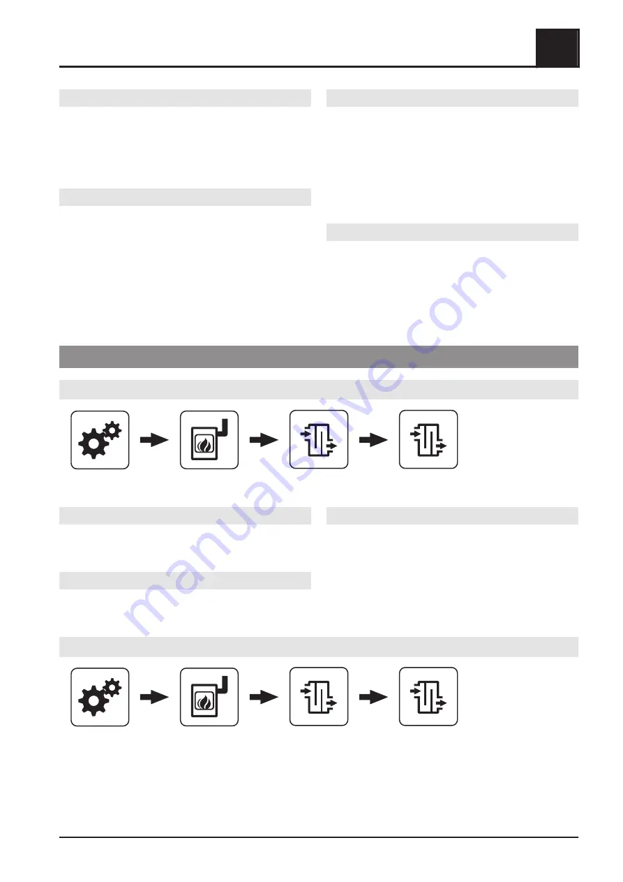
Heat exchanger configuration
System menu
Boiler
Heat exchanger
Heat exchanger configuration
Heat exchanger cleaning interval
Specifies how long the feed screw must feed until the
WOS drive is activated (“heat exchanger cleaning runtime"
parameter).
Heat exchanger cleaning runtime
Specifies the runtime of the WOS drive within the set time
window (“heat exchanger cleaning activated from" and
“heat exchanger cleaning activated until” parameter).
WOS speed, manual
WOS drive speed for use with the speed monitor
Manual heat exchanger
System menu
Boiler
Heat exchanger
Manual heat exchanger
The menu is used to test and calibrate the WOS. The calibration is only possible if the corresponding inputs and
outputs are configured.
⇨ See "Perform hardware detection manually" [page 24]
Menus and parameters
5
Boiler
Service manual SPS 4000 | B0960622_en
51


