Hydraulic bunker cover
Specifies the number of hydraulic bunker covers.
External control
Specifies the number of externally controlled discharges.
Discharge / configurations
System menu
System
configuration
Fuel
feed
Discharge /
configuration
Menu for configuring the individual components of the discharge system and for setting the sequence. The
entries in this menu depend on the settings in the “Feeder unit” and “Chamber discharge system” menus.
... is loaded by
Specifies the feeder unit from which the selected
component is loaded.
Safety group...
Assigns the relevant component to a safety group. The
setting must be carried out according to the wiring or
electrical diagram.
... permanently active
If this parameter is activated, this conveyor always
conveys the material to the material transport, even if the
boiler does not request any material. The parameter is
then used when two material consumers (e.g. multi-boiler
systems) should be filled even when the system is
switched off.
It is recommended that the sequence always be carried out from the lock to the discharge system. This normally
corresponds to the wiring in the circuit diagram and the order of the menu entries from top to bottom. It should
be noted that a screw of the chamber discharge system must also be parameterised as a feed screw.
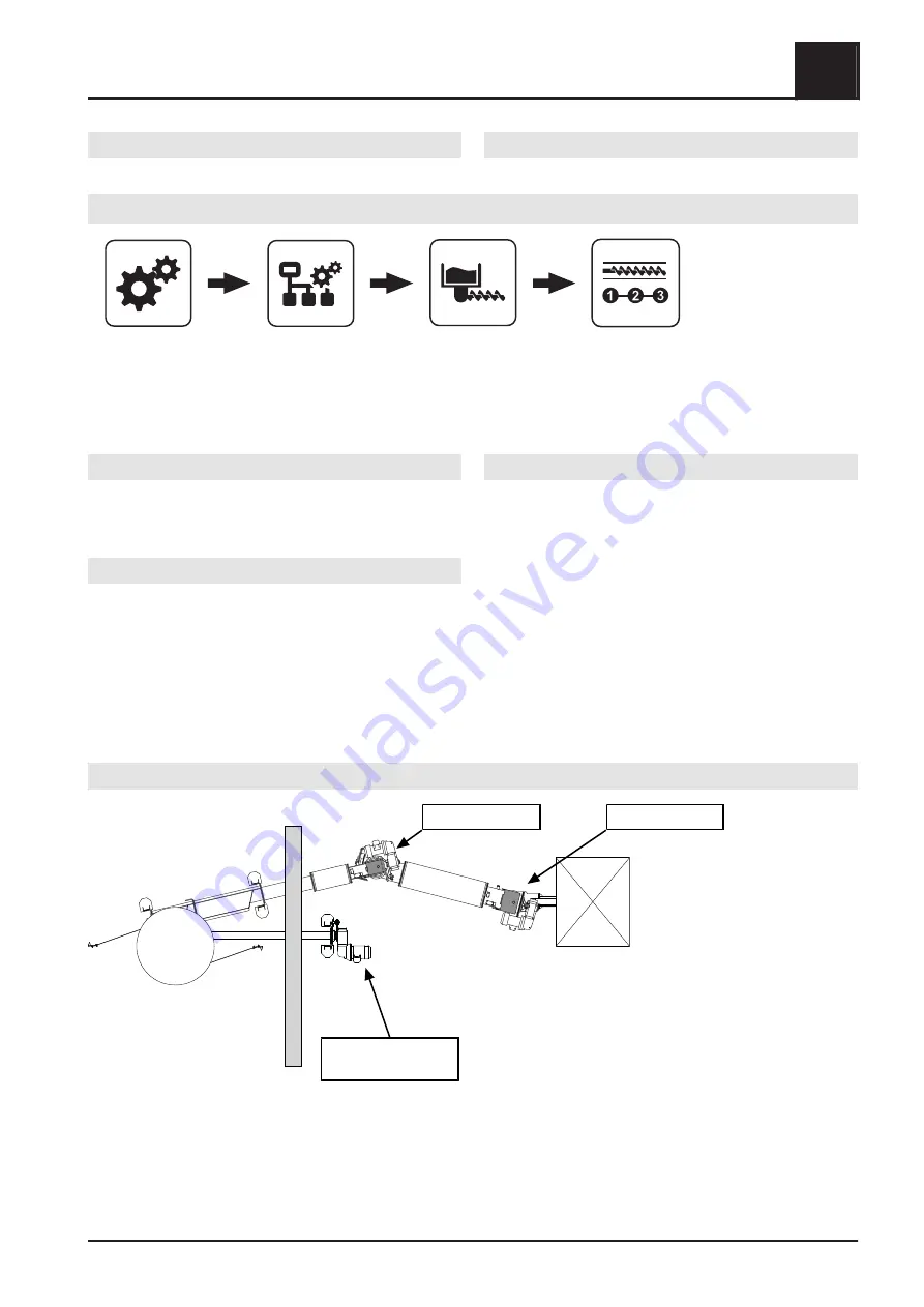
Example 1 - rotary agitator with separate drive and two feed screws
Rotary agitator
separately driven
Feed screw 1
Feed screw 2
Menus and parameters
5
System configuration
Service manual SPS 4000 | B0960622_en
81


