58
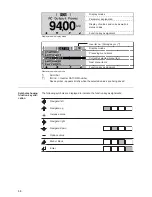
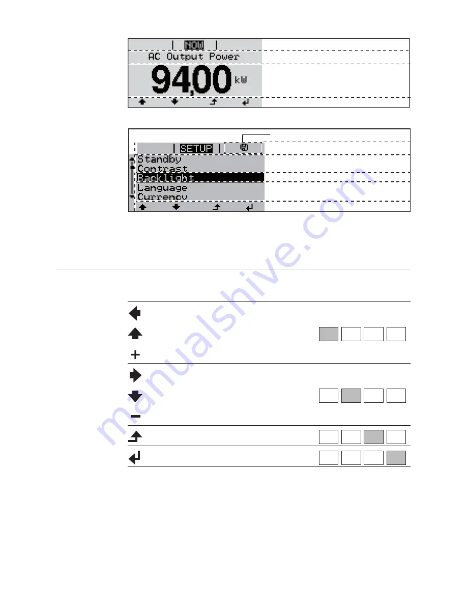
Display areas in display mode
Display areas in setup mode
(*)
Scroll bar
(**)
INV no. = Inverter DATCOM number,
Save symbol - appears briefly while the selected values are being saved
Symbols showing
function key allo-
cation
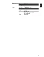
The following symbols are displayed to indicate the function key assignments:
Function key assignment
Display modes
Parameter explanation
Display of values and units as well as
status codes
Function key assignment
Next menu items
Currently selected menu item
Preceding menu items
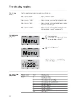
Display modes
Inverter no. | Storage sym. (**)
(*)
1
Navigate: left
Navigate: up
Increase value
Navigate: right
Navigate: down
Reduce value
Menu / Back
Enter
Summary of Contents for Agilo 100.0-3
Page 2: ...0...
Page 4: ...2...
Page 8: ...6...
Page 13: ...General information...
Page 14: ......
Page 30: ...28...
Page 31: ...Installation and commissioning...
Page 32: ......
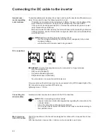
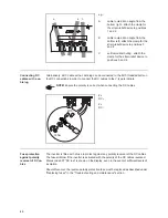
Page 51: ...49 EN 1 2 Inserting the fuse grounds the solar modules on the negative pole 1 1 1 2 2...
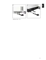
Page 53: ...51 EN 2 3 Tightening torque 3 Nm 1 3 2 4 5 4 3 2 4 5 1 5...
Page 57: ...Operation...
Page 58: ......
Page 84: ...82...
Page 85: ...Troubleshooting and maintenance...
Page 86: ......
Page 107: ...Appendix...
Page 108: ......

