background image

6

Summary of Contents for Agilo 100.0-3

Page 1: ...Perfect Charging Perfect Welding Solar Energy 42 0426 0163 EN 005 03122014 Fronius Agilo Outdoor 75 0 3 100 0 3 Operating Instructions Grid connected inverter EN...

Page 2: ...0...

Page 3: ...h the product Reading the instructions carefully will enable you to learn about the many different features it has to offer This will allow you to make full use of its advantages Please also note the...

Page 4: ...2...

Page 5: ...t 21 Data communication area 22 Possible relay contact functions 24 Data communication and Solar Net 26 Solar Net and data interface 26 Overcurrent and undervoltage cut out 26 Description of the Froni...

Page 6: ...the negative pole inserting a fuse 48 Closing the inverter 50 Closing the inverter 50 Using for the first time 52 Factory configuration 52 Using for the first time 52 Configuring the inverter for exis...

Page 7: ...the display 85 Class 1 status codes 85 Class 3 status codes 87 Class 4 status codes 88 Class 5 status codes 94 Class 7 status codes 96 Class 10 12 status codes 99 Customer service 99 Maintenance 100...

Page 8: ...6...

Page 9: ...injury or death to the operator or a third party damage to the device and other material assets belonging to the operat ing company inefficient operation of the device All persons involved in commissi...

Page 10: ...ll be deemed as not in accordance with the intended purpose The manufacturer shall not be held liable for any damage arising from such usage For exact information on permitted environmental conditions...

Page 11: ...e public low voltage mains EMC device classification as per the rating plate or technical data In certain cases even though a device complies with the standard limit values for emissions it may affect...

Page 12: ...entation To comply with the European Directive 2002 96 EC on Waste Electrical and Electronic Equipment and its implementation as national law electrical equip ment that has reached the end of its life...

Page 13: ...General information...

Page 14: ......

Page 15: ...In the event of abnormal grid conditions the inverter shuts down immediately according to national standards and guidelines and stops feeding energy into the grid e g in the event of grid disconnecti...

Page 16: ...fety symbols Text of the warning notices WARNING Risk of serious injury and damage due to incorrect operation Do not use the functions described here until you have fully read and understood the follo...

Page 17: ...15 EN An electric shock can be fatal Make sure that both the input side and output side of the device are de energised before opening the device Wait for the capacitors to discharge 10 minutes...

Page 18: ...complying with all the instructions in the operating instructions performing all stipulated inspection and maintenance work Application area The inverter has been developed exclusively for use in gri...

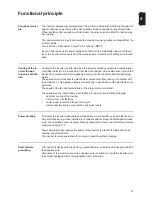
Page 19: ...he electronics compartment from coming into contact with the ambient air This approach largely prevents any contamination of the electronics com partment The speed of the fan and temperature of the in...

Page 20: ...ion and to making the system data avail able at all times The inverter has a range of basic functions for logging minimum and maximum values on a daily and total basis The values are output on the dis...

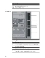
Page 21: ...main switch lockable when switched off IMPORTANT The door cannot be opened when the DC main switch is switched on 5 Door 6 Control elements display buttons monitoring and status LEDs 7 Exhaust air ho...

Page 22: ...r inlet grille 2 Data communication area 3 Fuse holder for operation with solar modules grounded to the negative pole DC to PE 4 2 pin automatic circuit breaker to protect the AC power supply 5 4 pin...

Page 23: ...for attaching the strain relief clamps for the DC cable 5 Cable input opening with sliding cover and seal 6 Openings for attaching the strain relief clamps for the AC cable 7 Grounding terminal for AC...

Page 24: ...r DATCOM components e g in verter sensor box etc 4 Solar Net OUT connection socket Fronius Solar Net output for connecting to other DATCOM components e g in verter sensor box etc 5 VSR connection sock...

Page 25: ...contact 5 6 IN2 for connecting and evaluating a floating alarm contact 7 8 IN3 for connecting and evaluating a floating alarm contact The contacts must be potential free Contact rating 24 V 10 mA Cabl...

Page 26: ...ent functions in the Basic service menu The access code 22742 must be entered to access the Basic service menu Press the Menu key Select Setup mode Press the unassigned Esc button five times Enter the...

Page 27: ...non return valve Warning Defined warning sta tus codes Error confirmation at the touch of a button NO alarm contact activation when cer tain warning status codes occur at a specific frequency accordin...

Page 28: ...ence of an undervoltage check some of the other DATCOM com ponents as required The Fronius Solar Net LED flashes briefly every 5 seconds following a shutdown as the result of an overcurrent or undervo...

Page 29: ...IG Plus with a Fronius Com Card 1 Fronius Datalogger Web with LAN interface for connecting to a PC laptop 1 Fronius Public Display Box 1 external display Communication between the individual component...

Page 30: ...28...

Page 31: ...Installation and commissioning...

Page 32: ......

Page 33: ...ter Cabling into the inverter The AC cable DC cable and the data communications cable if required can be fed into the inverter as follows a from below e g via a cable duct or a false floor maximum cab...

Page 34: ...rances between the inverter and a wall Wall left side of inverter min 400 mm to permit the door to be opened fully min 50 mm to open the door 90 Wall right side of inverter min 200 mm to permit the ai...

Page 35: ...ng a pallet fork forklift truck or lift truck WARNING Falling equipment can cause serious or even fatal injury When transporting the inverter using a crane always use all four of the lifting eyes prov...

Page 36: ...ck Removing the front base cover Removing the rear base cover 1 2 4 3 5 1 2 5 3 4 WARNING Equipment that falls or topples over can cause serious or even fatal injury always insert the fork into the fo...

Page 37: ...nverter horizontally using the leveling feet The leveling feet are located at the bottom of the inverter for better accessibility op tionally remove the left and right base cover Depending on the acce...

Page 38: ...nction with ferrules only Fine core cables without ferrules may only be connected to the M10 threaded bolts of the mains connections using a suitable M10 cable lug tightening torque 18 Nm Connecting a...

Page 39: ...e to the inverter as the result of incorrectly tightened ca ble connections Incorrectly tightened cable connections can cause heat damage to the inverter that may result in a fire When connecting AC a...

Page 40: ...nductor the neutral conductor and the ground conductor 3 Push the AC terminal up and over the grid connection and the bare end of the cable Tighten the AC terminal 5 mm Allen key Tightening torque 12...

Page 41: ...the clamp for the strain relief device to positions 5 and 6 Connecting AC cables with a ca ble lug Alternatively an AC cable with a cable lug can be connected to the M10 threaded bolts on the mains c...

Page 42: ...ernal AC supply for the inverter e g to provide an external supply to controllers or fans 1 2 If present connect ground conductor to grounding terminal 9 3 5 6 9 2 4 1 7 8 18 Nm M10 M10 Inverter Phase...

Page 43: ...ave adequate insulation resistance Fit overvoltage protection to the DIN rail on the DC side according to the manufactur er s instructions Fit a grounding terminal to the DIN rail on the DC side Remov...

Page 44: ...lug on the AC connection side Max cable cross section must comply with the instructions of the overvoltage protection manufacturer Open the M20 screw joints Feed the cable through Connect the cable t...

Page 45: ...matic circuit breaker in the correct phase se quence Connect the overvoltage protection to the grounding terminal If available connect the remote contacts of the overvoltage protection device with two...

Page 46: ...ctor shaped single wire SM sector shaped multi strand fine core cables in conjunction with ferrules only Fine core cables without ferrules may only be connected to the M10 threaded bolts of the DC con...

Page 47: ...e Repeat this process for every DC cable Fit the contact protectors WARNING An electric shock can be fatal Danger due to grid voltage and DC voltage from solar modules that are exposed to light Make s...

Page 48: ...ons in order to connect the DC cables to the V type terminals 2x DC 2x DC Fuse protection against polarity reversal of DC ca bles The inverter is fitted with a fuse to protect against any polarity rev...

Page 49: ...A 1000 V fuse dimensions 10 x 38 mm IMPORTANT Fuses for grounding the solar module are not part of the scope of supply of the inverter If the manufacturer of the solar module stipulates that groundin...

Page 50: ...tiviert Die Solarmodule sind geerdet Vor Arbeiten an der Photovoltaik Anlage AC und DC Seite spannungsfrei schalten Warnung Ein elektrischer Schlag kann t dlich sein Gefahr durch DC Spannung von den S...

Page 51: ...49 EN 1 2 Inserting the fuse grounds the solar modules on the negative pole 1 1 1 2 2...

Page 52: ...ection can cause serious inju ry or damage The screws on the air inlet grille and on the covers provide a suitable ground con ductor connection for the housing these screws must not under any circumst...

Page 53: ...51 EN 2 3 Tightening torque 3 Nm 1 3 2 4 5 4 3 2 4 5 1 5...

Page 54: ...enter the startup phase The inverter is about to start up automatically Once the inverter has completed its automatic startup the operating state LED will show steady green Provided that energy contin...

Page 55: ...r DC operating mode is displayed the set time starts flashing Press the Enter key The time is applied and the date now ap pears DD MM YYYY the day field starts flashing Use the Up and Down keys to sel...

Page 56: ...ystem no solar mod ule grounding Factory setting Use the up or down buttons to se lect the Negative grounding method Negative solar module grounded on the negative pole Press the Enter key The Negativ...

Page 57: ...Operation...

Page 58: ......

Page 59: ...ng state LED green for displaying the operating state Function keys allocated different functions depending on the selection 5 Left up key for navigating to the left and up 6 Down right key for naviga...

Page 60: ...following symbols are displayed to indicate the function key assignments Function key assignment Display modes Parameter explanation Display of values and units as well as status codes Function key a...

Page 61: ...nergy into the grid While error handling the inverter waits for an ac knowledgement or for an error to be rectified 2 orange lights up The inverter will enter its automatic startup or self test phase...

Page 62: ...grid conditions according to national regulations are tested Depending on the country specific regulations the startup test can last just a few sec onds or take several minutes During the startup phas...

Page 63: ...splay backlighting switches off automatically and the inverter switches to display mode NOW assuming the display backlighting is set to automatic The switchover to the NOW display mode can happen from...

Page 64: ...the current calendar year Display mode TOTAL Displays values for energy fed into the grid since the inverter was originally commissioned Open menu level Use the left and right keys to select the requ...

Page 65: ...ate TODAY YEAR kWh MWh Energy Supplied Day characteristic TODAY TOTAL Currency Yield g kg CO2 saving W Max output power V Max three phase AC grid voltage V Max PV array voltage HH MM Operating hours D...

Page 66: ...ently being fed into the grid Press the Enter key to display the day character istic Day characteristic Displays a plot showing the power output during the day The time axis is scaled automatically Pr...

Page 67: ...mbient Temperature Temperature of the air sucked in to cool the invert er C Fan Speed rpm Time If the time is changed on an inverter or a system add on it will also be changed in any other devic es th...

Page 68: ...ergy Supplied Energy fed into the grid during the period in ques tion kWh MWh Press the Enter key to display the day character istic only in display mode TODAY Day characteristic Displays a plot showi...

Page 69: ...educed during the period in question g kg The value for CO2 savings depends on the power station facilities and corresponds to the CO2 emissions that would be released when generating the same amount...

Page 70: ...working HH MM Although the inverter does not operate during the night the data required for the Sensor Box option is logged and stored 24 hours a day IMPORTANT A prerequisite for the correct display o...

Page 71: ...the preferences and requirements of the user Accessing the setup menu Move up and down the menu items SETUP menu level selected Switch to the menu level press the Menu key Select Setup mode using the...

Page 72: ...ode is now active The Startup LED shows steady orange Resuming feeding energy into the grid STANDBY and ENTER appear alternately on the display when in Standby mode Press the Enter key to resume feedi...

Page 73: ...easurement Input of a unit k M ON The display backlighting remains permanently on when the in verter is switched on OFF The display backlighting is permanently switched off IMPORTANT The Backlight men...

Page 74: ...displaying the settings that will be of relevance to an energy supply company The val ues shown will depend on the country setup or the device specific settings of the inverter Setting range k M Fact...

Page 75: ...Upper inner grid frequency in Hz FIL min Lower inner grid frequency in Hz FOL max Upper outer grid frequency limit value in Hz FOL min Lower outer grid frequency limit value in Hz LVFRT Status Status...

Page 76: ...eys to scroll through the list Press the Back key to close the status and fault list Grid Status The five most recent grid faults can be displayed Press the Enter key to see the five most recent grid...

Page 77: ...75 EN Unit Display area Display Display Software Interface SmartMedia Card Con trol Control Software Monitoring Monitoring Software Inter face Factory setting...

Page 78: ...ess Enter The second digit of the value flashes Repeat steps 4 and 5 until the whole value to be set flashes Press Enter Repeat steps 4 6 as required for units or other values that are to be set until...

Page 79: ...es Setting the display backlighting Setting the currency and feed in tariff Setting the time and date Setting the dis play backlighting Setting the cur rency and feed in tariff Select the Backlight me...

Page 80: ...he selected currency starts flashing Press the Enter key The currency is applied and the present feed in tariff in currency kWh displayed factory setting 0 43 EUR kWh the first digit starts flashing U...

Page 81: ...ashing Use the Up and Down keys to select a value for the hour Press the Enter key The minutes field starts flashing Repeat steps 3 and 4 for the minutes and seconds until the set time starts flashing...

Page 82: ...arts flashing Repeat steps 7 and 8 for the month and the last 2 digits of the year until the set date starts flashing Press the Enter key The date is applied and the Time menu item is displayed 9 10 D...

Page 83: ...Code is displayed in the CODE menu the first digit starts flashing Enter the code 12321 use the Up and Down keys to select a value for the first digit of the code Press the Enter key The second digit...

Page 84: ...82...

Page 85: ...Troubleshooting and maintenance...

Page 86: ......

Page 87: ...monitoring period If no further problem has been detected by the end of this period then the inverter will resume feeding energy into the grid Depending on the country setup the SoftStart function GP...

Page 88: ...rgy into the grid Remedy Check grid connections If this status code keeps recurring contact your system engi neer 107 No AC grid Behaviour Following careful testing and when the grid conditions are wi...

Page 89: ...overtemperature The inverter resumes with its startup routine Remedy Purge cooling air openings and heat sink if necessary fault is rectified automatically If this status code keeps recurring contact...

Page 90: ...term interruption while feeding energy into the grid due to a grid fault or a power module fault The inverter resumes with its startup routine Remedy Fault is rectified automatically If this status co...

Page 91: ...Behaviour The inverter is disconnected from the grid for safety reasons Remedy Fault is rectified automatically If this status code keeps recurring notify a Fronius trained ser vice engineer 416 No co...

Page 92: ...r resumes with its startup routine Remedy Fault is rectified automatically If this status code keeps recurring contact your system engi neer 437 General error handling started in the power stage set B...

Page 93: ...ify a Fronius trained service engineer 461 Fault in the DSP data memory Behaviour The inverter is not feeding any energy into the grid Remedy If the status code is displayed all the time notify a Fron...

Page 94: ...ius trained service engineer 488 AC measurement device is faulty Behaviour The inverter is not feeding any energy into the grid Remedy notify a Fronius trained service engineer 490 491 Internal commun...

Page 95: ...e engineer 497 The 14 V or 22 V supply voltage for the PWM driver is faulty Behaviour The inverter is not feeding any energy into the grid Remedy notify a Fronius trained service engineer 498 The 24 V...

Page 96: ...been satisfied If the status code is displayed all the time notify a Fronius trained service engineer 516 No communication possible with the storage unit Description Storage unit warning message Remed...

Page 97: ...e inverter Remedy Update the inverter firmware using the Fronius Solar update software the latest inverter firmware is available from http www fronius com If the status indicator appears all the time...

Page 98: ...716 Provides information about the internal processor program status Description Is of no concern when the inverter is working properly and only appears in the Status PS setup parameter In the event o...

Page 99: ...tion Warning message is shown on the display the inverter is not feeding any energy into the grid Remedy If the status code is displayed all the time notify a Fronius trained service engineer 761 765...

Page 100: ...n on the display Remedy Press the Enter key to acknowledge the error If the status code is displayed all the time notify a Fronius trained service engineer 776 Invalid device type Description Warning...

Page 101: ...inverter is working properly and only appears in the Status PS setup parameter In the event of an actual error this status code assists Fronius Technical Support during the error analysis IMPORTANT C...

Page 102: ...the Fronius Agilo Service Manual apply to the relevant TechSupport for components Opening the in verter for mainte nance work When the inverter must be opened for maintenance work carry out the follow...

Page 103: ...ject to heavy accumu lations of dust When operating in environments subject to heavy accumulations of dust if necessary purge the filter grilles on the fans using clean compressed air check all 6 mont...

Page 104: ...discharge Discharge time is 5 minutes WARNING An electric shock can be fatal Danger due to DC voltage from the so lar modules The DC main switch is only to be used to de energise the power stage set G...

Page 105: ...bbon cable Unplug the 8 pin Molex plug 8p Unplug the 2 pin Molex plug 2p 1 Remove 16 screws Pull out the bottom cover and remove from the front Open the fuse holder 1 Fit the spare fuse in the fuse ho...

Page 106: ...the cover in place using 16 screws Tightening torque 3 Nm 1 Connect the ribbon cable Connect the 8 pin Molex plug 8p Connect the 2 pin Molex plug 2p 1 Fit the contact protection above the data commun...

Page 107: ...Appendix...

Page 108: ......

Page 109: ...ortion 3 Power factor cos phi 1 0 8 1 ind cap 2 Max permitted mains impedance Zmax at PCC3 66 mOhm Max feedback current4 0 A5 Starting current pulse6 0 A5 Max output fault current per period 522 A 2 4...

Page 110: ...Power factor cos phi 1 0 8 1 ind cap 2 Max permitted mains impedance Zmax at PCC3 52 mOHM Max feedback current4 0 A5 Starting current pulse6 0 A5 Max output fault current per period 522 A 2 47 ms Maxi...

Page 111: ...or device specific settings ind inductive cap capacitive 3 PCC interface to the public grid 4 Maximum current from the inverter to the solar module when an error occurs in the inverter or when the in...

Page 112: ...tion of in plant generation systems with the low voltage grid published by the German Electricity Industry Association VDEW technical guidelines for parallel operation of in plant generation systems p...

Page 113: ...the engi neer installing the system or on the Internet at the following address http www fronius com solar servicebasic de To make a claim under the Fronius manufacturer s warranty the relevant produ...

Page 114: ...d all addresses of our sales branches and partner firms Fronius International GmbH 4600 Wels Froniusplatz 1 Austria E Mail pv sales fronius com http www fronius com Fronius USA LLC Solar Electronics D...

Reviews: