background image

3

EN

Explanation of symbols

Explanation of 
safety symbols

If you see any of the symbols depicted in the "Safety rules" chapter, special care is re-
quired.

Explanation of 
symbols and 
choice of location

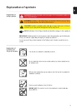
DANGER! 

Indicates immediate and real danger. If it is not avoided, death or se-

rious injury will result.

WARNING! 

Indicates a potentially dangerous situation. Death or serious injury 

may result if appropriate precautions are not taken.

CAUTION! 

Indicates a situation where damage or injury could occur. If it is not 

avoided, minor injury and/or damage to property may result.

NOTE! 

Indicates a risk of flawed results and possible damage to the equipment.

IMPORTANT! 

Indicates tips for correct operation and other particularly useful information. 

It does not indicate a potentially damaging or dangerous situation.

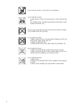
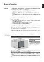
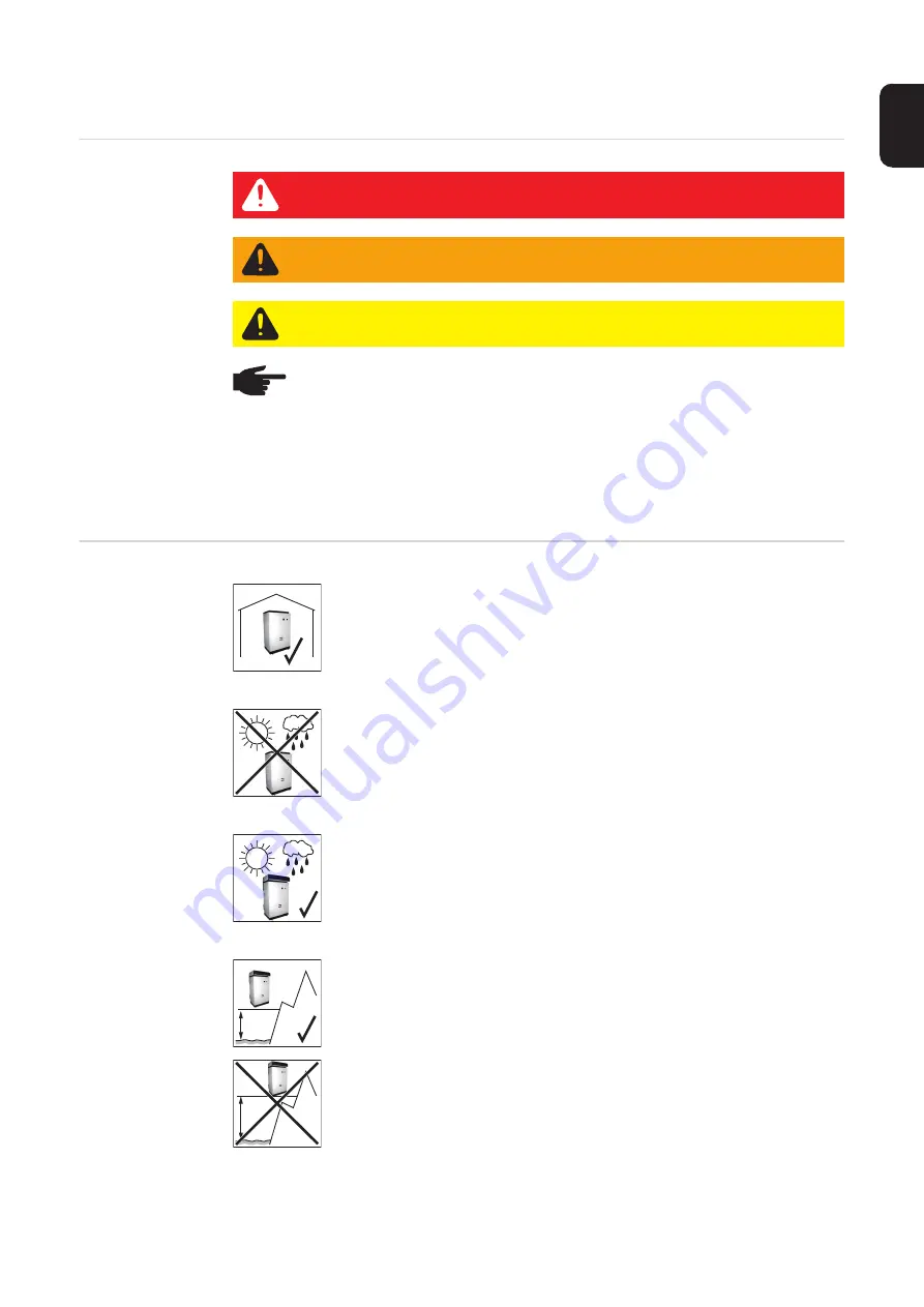
The inverter is suitable for installation indoors.

Do not install the indoor device outside without an inlet air attachment or 
an outlet air unit.

With an inlet air attachment and outlet air unit, the inverter is suitable for 
installation outdoors.

Can be used at altitudes of up to 3000 m

IMPORTANT!

 The inverter must not be installed or used at altitudes 

above 3000 m. 

IP 44

max. 
3000 m

INDOOR / OUTDOOR

> 3000 m

INDOOR
OUTDOOR 

Summary of Contents for Agilo TL

Page 1: ...g Perfect Welding Solar Energy 42 0426 0177 EN 001 18112014 Fronius Agilo TL Explanation of symbols and choice of location Notes regarding installation and connection Operating Instructions Grid conne...

Page 2: ...0...

Page 3: ...ction area 8 Connecting aluminium cables 8 Max cross section of AC cables 8 Fuse protection on alternating current side 8 Notes regarding DC connection 9 General comments regarding solar modules 9 DC...

Page 4: ...2...

Page 5: ...ided minor injury and or damage to property may result NOTE Indicates a risk of flawed results and possible damage to the equipment IMPORTANT Indicates tips for correct operation and other particularl...

Page 6: ...in places where there is an increased risk of damage from farm ani mals horses cattle sheep pigs etc in stables or adjoining areas in storage areas for hay straw chaff animal feed fertilisers etc Do n...

Page 7: ...are operated within their permitted operating ranges at all times Observe all the measures recommended by the solar module manufacturer to ensure long term retention of the solar module s properties...

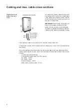
Page 8: ...the AC DC cables and the data communication cables The maximum cable cross section for AC and DC cables is 240 mm In total 6 DC cables 6 DC cables and 6 AC cables 2x L1 2x L2 2x L3 can be fed into th...

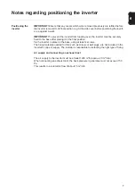
Page 9: ...ixed to the base after placing it in the final position Fix the inverter in place on the base using at least 4 screws The fixing materials needed for this such as screws or wall plugs are not included...

Page 10: ...of the alternating current on the medium voltage side depends on the transformer available and is to be designed accordingly by the installation engineer IMPORTANT The resistance in the leads to the A...

Page 11: ...tively using an M12 cable lug IMPORTANT Only the following cables may be connected to V type terminals RE round single wire RM round multi strand SE sector shaped single wire SM sector shaped multi st...

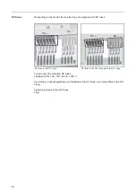
Page 12: ...uses the following DC fuses Littelfuse SPFJ 125 160 200 A 1000 V According to national guidelines and standards the DC fuses can only be fitted in the DC string Tightening torque of the DC fuses 7 Nm...

Page 13: ...e protection for the DC side and the DC side as standard AC side 3 x Raycap Strikesorb 40 C 1 x Raycap Strikesorb 40 F in a Y circuit SPD Class I according to IEC 61643 1 SPD Type 2 according to UL 14...

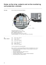
Page 14: ...ontact 1 SC1 Relay contact 1 NO1 NO for relay contact 1 NC2 NC for relay contact 2 SC2 Relay contact 2 NO2 NO for relay contact 2 The relay outputs are not fuse protected Relay contacts can be assigne...

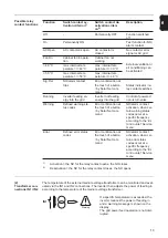
Page 15: ...on air conditioning can be activated 40 C max internal tem perature 40 C max internal tem perature 30 C 50 C max internal tem perature 50 C max internal tem perature 40 C Sig Rel NO alarm contact trip...

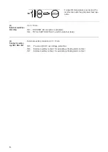
Page 16: ...DBY AC contactor is activated IN4 TOTAL SHUT DOWN AC and DC side shut down 4 Contact monitor ing IN5 IN6 IN7 External auxiliary contacts 24 V 10 mA IN5 Pre wired for DC overvoltage protection IN6 Exte...

Page 17: ...15 EN...

Page 18: ...d all addresses of our sales branches and partner firms Fronius International GmbH 4600 Wels Froniusplatz 1 Austria E Mail pv sales fronius com http www fronius com Fronius USA LLC Solar Electronics D...

Reviews: